01. About Spresense
Overview
The NEQTO Engine installed on the Spresense makes it easy to connect to NEQTO Console and the customer's cloud environment. It also allows customers to easily control sensors and devices via physical interfaces.
It has the following features:
- Wi-Fi and LTE (Cat-M1) communications are supported.
- Onboard antenna
- 4.75 V - 5.25 V Operating voltage range.
System Configuration
The hardware configuration varies depending on the communication type used.
Spresense Wi-Fi
Utilizes Wi-Fi communication.
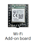
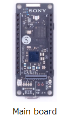
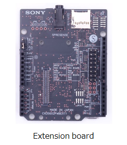
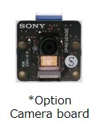
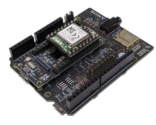
The configuration consists of a Spresense main board, a Spresense extension board, a Spresense Wi-Fi Add-on board iS110B, and an optional Spresense camera board.
 |
+ |  |
+ |  |
+ |  |
List of components
| Item | Model Name | Notes |
|---|---|---|
| Spresense main board | CXD5602PWBMAIN1 | |
| Spresense extension board | CXD5602PWBEXT1 | |
| Spresense Wi-Fi Add-on board | iS110B Board Version: - V1.0C - V1.0B * - V1.0A * | Depending on the board version, software settings may need to be changed. For details on the setting command, refer to here. In addition, please check the board version from here (JA only). * The UART interface is not available on these board versions. There is a way to modify the Wi-Fi Add-on board to change it to the V1.0C interface. See here (JA only) for details on the modification. Please note that it is not covered by the warranty. |
| Spresense camera board | CXD5602PWBCAM1 |
Please refer to the following for the connection method of each board:
- How to attach the Spresense extension board and the Spresense main board
- How to attach the Spresense Wi-Fi Add-on Board iS110B (JA only)
- How to connect and prepare the Spresense main board and Spresense camera board
Spresense LTE-M
Utilizes LTE (Cat-M1) communication.
The configuration consists of a Spresense main board, a Spresense LTE extension board, and an optional Spresense camera board.
|
+ |  |
+ | |
List of components
| Item | Model Name | Notes |
|---|---|---|
| Spresense main board | CXD5602PWBMAIN1 | |
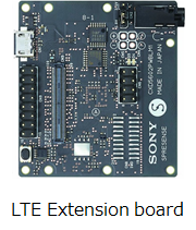
| Spresense LTE extension board | CXD5602PWBLM1 | Supports LTE Cat-M1 |
| Spresense camera board | CXD5602PWBCAM1 |
Please refer to the following for the connection method of each board:
- How to attach the Spresense LTE extension board and the Spresense main board
- How to connect and prepare the Spresense main board and Spresense camera board
Main Specifications
 |
Spresense Wi-Fi | 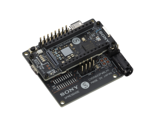 |
Spresense LTE-M |
| Item | Specifications | |
|---|---|---|
| Spresense Wi-Fi | Spresense LTE-M | |
| CPU | ARM® Cortex®-M4F x 6 cores | |
| SRAM (Internal RAM) | 1.5 MB | |
| Flash memory (External memory) | 8 MB | |
| Digital I/O |
Spresense main board :
I2C x 1 ch *Duplicate signals UART x 1 ch *Note 1 GPIO x 5 ch GPIO (LED) x 2 ch System LED x 2 ch Spresense extension board : UART x 1 ch *Note 1 I2C x 1 ch *Duplicate signals SPI x 1 ch GPIO x 4 ch GPIO (PWM capable) x 2 ch GPIO (PWM capable) x 2 ch or I2C x 1 ch |
Spresense main board :
I2C x 1 ch UART x 1 ch GPIO x 5 ch GPIO (LED) x 2 ch System LED x 2 ch Spresense LTE extension board : SPI x 1 ch GPIO x 2 ch GPIO (PWM capable) x 2 ch GPIO (PWM capable) x 2 ch or I2C x 1 ch GPIO (Push Switch) x 1 ch |
| Digital I/O Voltage | Spresense main board :
1.8 V Spresense extension board : 3.3 V and 5 V selectable *Note 2 |
Spresense main board :
1.8 V Spresense LTE extension board : 3.3 V and 5 V selectable *Note 3 |
| Analog Input | Spresense extension board :
ADC x 2 ch *Note 4 |
Spresense LTE extension board :
ADC x 2 ch *Note 4 |
| Communication Interface |
IEEE802.11b/g/n 2.4GHz band *Note 5 | LTE (Cat-M1) *Note 6
Band : 1, 8, 18, 19 |
| Main Power Supply | 5 V *Note 7 | |
| Operating Conditions | Temperature: 10 ℃ - 40 ℃
Humidity: 30 % - 80 % (No condensation) |
|
| Storage Conditions | Temperature: -20 ℃ - 60 ℃
Humidity: 10 % - 80 % |
|
Note 1) To utilize the UART interface in the Spresense Wi-Fi configuration, the Wi-Fi Add-on board iS110B board version
V1.0Cmust be used. In addition, the UART pins of the Spresense main board and the Spresense extension board are connected to the same UART signal lines. The UART pins from only one of these sources should be used. Please check here for details.Note 2) In the Spresense Wi-Fi configuration, the operating voltage of pin socket JP2 and JP13 on Spresense extension board can be set to 5V or 3.3V by changing the position of the jumper on JP1. Spresense extension board operating voltage is set to 5V when shipped. Please check here for details.
Note 3) In the Spresense LTE-M configuration, the operating voltage of pin header CN9 on the Spresense LTE extension board can be set to 5V or 3.3V by changing the position of the jumper on CN2. Spresense LTE extension board operating voltage is set to 5V when shipped. Please check here for details.
Note 4) The ADC supports HPADC. Please check here for details.
Note 5) Please check here (JA only) for the specifications of the Spresense Wi-Fi Add-on board iS110B.
Note 6) Please check here for the specifications of the Spresense LTE extension board and here for the list of tested LTE-M SIMs.
Note 7) Please refer to the following for the power supply method:
Pinout
The neqto.js interface that can be used with Spresense Wi-Fi and Spresense LTE-M is as follows:
Supported from FW version 01.03.00 or later.
(For pinout specifications of the previous FW version, please refer to here)
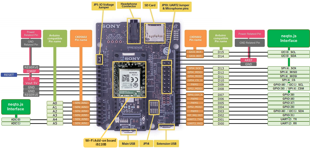
Spresense main board
In the Spresense Wi-Fi configuration, the signal pins attaching the Spresense Wi-Fi Add-on board iS110B will be occupied. If necessary, a structure to extend the signal lines will be required.
Spresense extension board
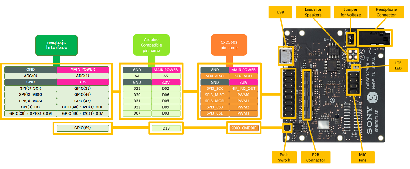
Spresense LTE extension board
neqto.js Interfaces
The following is a comparison table of the Spresense Pin List and the neqto.js interface:
The colored cells indicate the user interfaces that can be controlled from neqto.js.
| Pin No. | Pin Name | Arduino Pin Name | neqto.js Interfaces | |||||
|---|---|---|---|---|---|---|---|---|
| Spresense Wi-Fi | Spresense LTE-M | |||||||
| 29 | PIN_SPI2_MOSI | D04 | GPIO(29) | - | - | - | - | - |
| 30 | PIN_SPI2_MISO | D08 | GPIO(30) | SPI(4)_CSM | *1 | - | - | - |
| 31 | PIN_HIF_IRQ_OUT | D02 | GPIO(31) | - | - | GPIO(31) | - | - |
| 37 | PIN_SEN_IRQ_IN | D22 | GPIO(37) | - | - | GPIO(37) | - | - |
| 38 | PIN_SPI3_CS0_X | D32 | - | - | - | - | SPI(3)_CS | *1 |
| 39 | PIN_SPI3_CS1_X | D07 | GPIO(39) | - | - | GPIO(39) | SPI(3)_CSM | *1 |
| 41 | PIN_SPI3_SCK | D29 | - | - | - | - | SPI(3)_SCK | - |
| 42 | PIN_SPI3_MOSI | D31 | - | - | - | - | SPI(3)_MOSI | - |
| 43 | PIN_SPI3_MISO | D30 | - | - | - | - | SPI(3)_MISO | - |
| 44 | PIN_I2C0_BCK | D15 | - | I2C(0)_SCL | *2 | - | I2C(0)_SCL | - |
| 45 | PIN_I2C0_BDT | D14 | - | I2C(0)_SDA | *2 | - | I2C(0)_SDA | - |
| 46 | PIN_PWM0 | D06 | GPIO(46) <PWM#0,1> | - | *4 | GPIO(46) <PWM#0,1> | - | *4 |
| 47 | PIN_PWM1 | D05 | GPIO(47) <PWM#0,1> | - | *4 | GPIO(47) <PWM#0,1> | - | *4 |
| 48 | PIN_PWM2 | D09 | GPIO(48) <PWM#2,3> | I2C(1)_SCL | *5 | GPIO(48) <PWM#2,3> | I2C(1)_SCL | *5 |
| 49 | PIN_PWM3 | D03 | GPIO(49) <PWM#2,3> | I2C(1)_SDA | *5 | GPIO(49) <PWM#2,3> | I2C(1)_SDA | *5 |
| 67 | PIN_UART2_TXD | D01 | - | UART(2)_TX | *3 | - | UART(2)_TX | - |
| 68 | PIN_UART2_RXD | D00 | - | UART(2)_RX | *3 | - | UART(2)_RX | - |
| 69 | PIN_UART2_CTS | D27 | - | UART(2)_CTS | *3 | - | UART(2)_CTS | - |
| 70 | PIN_UART2_RTS | D28 | - | UART(2)_RTS | *3 | - | UART(2)_RTS | - |
| 71 | PIN_SPI4_CS_X | D10 | - | SPI(4)_CS | *1 | - | - | - |
| 72 | PIN_SPI4_SCK | D13 | - | SPI(4)_SCK | - | - | - | - |
| 73 | PIN_SPI4_MOSI | D11 | - | SPI(4)_MOSI | - | - | - | - |
| 74 | PIN_SPI4_MISO | D12 | - | SPI(4)_MISO | - | - | - | - |
| 89 | PIN_SDIO_CMDDIR | D33 | - | - | - | GPIO(89) PushSwitch | - | *6 |
| 93 | PIN_I2S0_BCK | D26 | GPIO(93) | - | - | GPIO(93) | - | - |
| 94 | PIN_I2S0_LRCK | D25 | GPIO(94) | - | - | GPIO(94) | - | - |
| 95 | PIN_I2S0_DATA_IN | D19 | GPIO(95) | - | - | GPIO(95) | - | - |
| 96 | PIN_I2S0_DATA_OUT | D18 | GPIO(96) | - | - | GPIO(96) | - | - |
| 97 | PIN_I2S1_BCK | LED0 | System LED1 | - | *7 | System LED1 | - | *7 |
| 98 | PIN_I2S1_LRCK | LED1 | System LED2 | - | *7 | System LED2 | - | *7 |
| 99 | PIN_I2S1_DATA_IN | LED2 | GPIO(99) | - | *8 | GPIO(99) | - | *8 |
| 100 | PIN_I2S1_DATA_OUT | LED3 | GPIO(100) | - | *8 | GPIO(100) | - | *8 |
| - | SEN_AIN0 | A4 | ADC(0) | - | - | ADC(0) | - | - |
| - | SEN_AIN1 | A5 | ADC(1) | - | - | ADC(1) | - | - |
- *1: SPI_CS and SPI_CSM are both SPI chip select signals. SPI_CSM is used for manual control of the chip select signal. For more details, please refer to here.
- *2: The I2C(0) signals on the Spresense main board and the Spresense extension board are duplicates.
- *3: To utilize the UART interface in the Spresense Wi-Fi configuration, the Wi-Fi Add-on board iS110B board version
V1.0Cmust be used. In addition, the UART pins of the Spresense main board and the Spresense extension board are connected to the same UART signal lines. The UART pins from only one of these sources should be used. Please check here for details. - *4: Can be used as GPIO or PWM output, however the function is switched in the corresponding Pin No.46-47 group. For example, if Pin No.46 is set to PWM, Pin No.47 will also be set to PWM.
- *5: Can be used as a GPIO, a PWM output, or an I2C pin, however the function is switched in the corresponding Pin No.48-49 group. For example, if Pin No.48 is set to PWM, Pin No.49 will also be set to PWM. The same applies when I2C is selected. Note that after opening I2C, the pin cannot be used as a GPIO port unless the CPU resets.
- *6: Connected to the Push Switch on the Spresense LTE extension board and can be controlled using GPIO functions. For GPIO operation mode, specify
2(IN). - *7: Connected to the LED on the Spresense main board and is used as the System LED.
- *8: Connected to the LED on the Spresense main board and can be controlled using GPIO functions. For GPIO operation mode, specify
5(OUT/PUSH-PULL)or4(OUT/PUSH-PULL/PULL-DOWN).
External Dimensions
| Item | Specifications | Notes |
|---|---|---|
| Spresense main board | 50 mm x 20.6 mm | Please check here for more details. |
| Spresense extension board | 68.6 mm x 53.3 mm | Please check here for more details. |
| Spresense LTE extension board | 45.0 mm x 50.0 mm | Please check here for more details. |
| Spresense camera board | 24.0 mm x 25.0 mm | Please check here for more details. |
| Spresense Wi-Fi Add-on board iS110B | approximately 23 mm x 20 mm | Please contact IDY for details. |
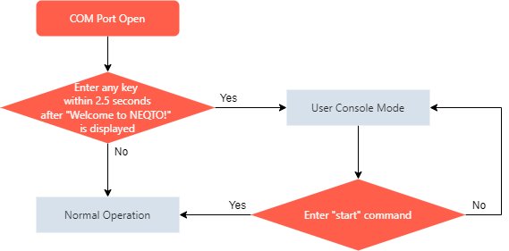
About User Console Mode
The User Console Mode provides a command console interface using the UART interface.
It is available for inputting various settings commands and displaying real-time logs.
After opening the COM port, Welcome to NEQTO! will be displayed. Then press any key on the keyboard within 2.5 seconds to activate the User Console Mode.
Appendix
[Archive] Pinout (FW version 01.02.00 or older)
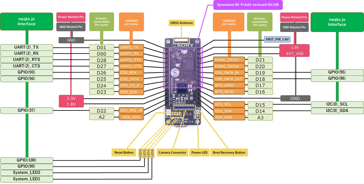
The following neqto.js interfaces are available for Spresense with the Spresense Wi-Fi Add-on board iS110B (manufactured by IDY) and the Spresense extension board mounted:
The I2C_SCL, I2C_SDA, and PWM x 4 marked with red frames are available.
Note that there are limitations when using the UART(TX/RX) marked with blue frames.
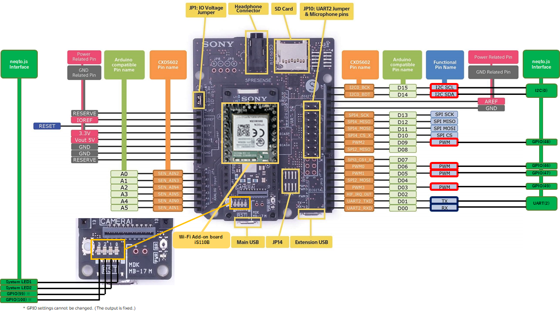
Fig. Spresense main board + Spresense extension board + Spresense Wi-Fi Add-on board iS110B
neqto.js Interfaces
The following is a comparison table of the Spresense Pin List and the neqto.js interface:
The colored cells are the user interfaces that can be controlled from neqto.js.
| Pin No. | Pin Name | Arduino Pin Name | Mode0 | Mode1 | Mode2 | Mode3 | neqto.js Interface |
|---|---|---|---|---|---|---|---|
| 44 | PIN_I2C0_BCK | D15 | GPIO | I2C#0 | - | - | I2C(0) |
| 45 | PIN_I2C0_BDT | D14 | GPIO | - | - | ||
| 46 | PIN_PWM0 | D06 | GPIO | PWM#0,1 | - | - | GPIO(46) *1 |
| 47 | PIN_PWM1 | D05 | GPIO | - | - | GPIO(47) *1 | |
| 48 | PIN_PWM2 | D09 | GPIO | PWM#2,3 | I2C#1 | - | GPIO(48) *1 |
| 49 | PIN_PWM3 | D03 | GPIO | - | GPIO(49) *1 | ||
| 67 | PIN_UART2_TXD | D01 | GPIO | UART#2 | - | - | UART(2) *2 |
| 68 | PIN_UART2_RXD | D00 | GPIO | - | - | ||
| 97 | PIN_I2S1_BCK | LED0 | GPIO | I2S#1 | - | - | System LED1 *3 |
| 98 | PIN_I2S1_LRCK | LED1 | GPIO | - | - | System LED2 *3 | |
| 99 | PIN_I2S1_DATA_IN | LED2 | GPIO | - | - | GPIO(99) *4 | |
| 100 | PIN_I2S1_DATA_OUT | LED3 | GPIO | - | - | GPIO(100) *4 |
- *1: Can be used as a GPIO or a PWM output pin, however the function is switched in corresponding Pin No.46-47 and Pin No.48-49 groups. For example, if Pin No.46 is set to PWM, Pin No.47 will also be set to PWM.
- *2: To utilize the UART interface in the Spresense Wi-Fi configuration, the Wi-Fi Add-on board iS110B board version
V1.0Cmust be used. In addition, the UART interface of the Spresense main board and the Spresense extension board cannot be used simultaneously. - *3: Connected to the LED on the Spresense main board and is used as the System LED.
- *4: Connected to the LED on the Spresense main board and can be controlled using GPIO functions. For GPIO operation mode, specify
4(OUT/PUSH-PULL/PULL-DOWN).