02. NEQTO Bridge Wi-Fi Module Initial Setup
Introduction
Hereinafter, "NEQTO Bridge device" is called "device", and "NEQTO Bridge Wi-Fi Module" is called "module". "NEQTO Bridge IO Board" or "NEQTO Bridge Digital IO Board" is called "IO board".
The following describes the procedure when using the module and the IO board.
Before beginning the initial setup, please review the supported communication specifications:
Wi-Fi authentication method supports only WPA/WPA2-Persoanl.
Initial Setup
To perform the initial setup, follow the steps below:
Prepare a Windows PC with TeraTerm (Terminal software) installed in advance, and start the module in User Console mode.
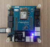
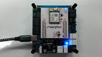
While pressing the User SW on the IO board, connect the device and PC via USB.
Use the USB cable for communication.The device's red and blue system LEDs will turn on at the same time.
If the two LEDs do not turn on, disconnect the USB from the PC and repeat from step 1.
Start TeraTerm and open the COM port.
When the USB is connected to a PC for the first time, the FTDI USB serial conversion driver is automatically installed and a COM port is created.
If the driver is not installed automatically, download the VCP driver for Windows from here and install it.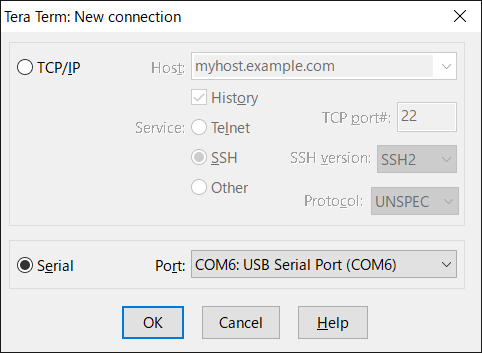
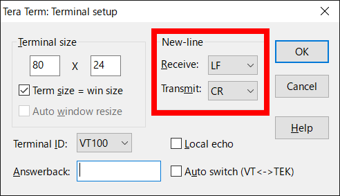
Set the serial port and terminal settings as shown below.
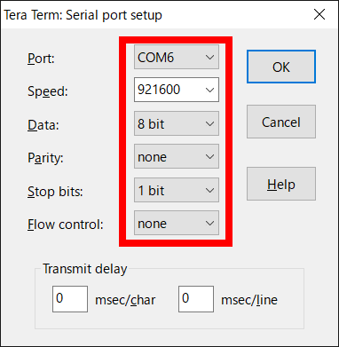
The User Console mode will start up, and a prompt will appear when the enter key is pressed.
If no prompt appears, disconnect the USB from the PC and repeat from step 1.
> ↵
> ↵
>
Configure the communication settings for the device.
Set the required configurations using the commands below.
The set value will be immediately saved in the nonvolatile memory after the command is input.List of communication setting commands
Command Content Note wifi set ssid <SSID> Sets the SSID of the Wi-Fi connection point.
31 character limit.
If <SSID> is omitted, the setting value will be blank.
Caution: If there are two or more spaces in a row, one space is used.wifi set pass <PASS> Sets the password to connect to the Wi-Fi.
A valid password must be 8-32 characters.
If <PASS> is omitted, the setting value will be blank.wifi get Gets the Wi-Fi connection setting information (SSID, Password).
If a setting value is blank, nothing is set.The following are example command inputs:
> wifi set ssid AP-TEST-g↵
OK
> wifi set pass 1234567890Abc↵
OK
> wifi get↵
[0]SSID : AP-TEST-g
[0]PASSWORD : ********
[1]SSID :
[1]PASSWORD :
[2]SSID :
[2]PASSWORD :
[3]SSID :
[3]PASSWORD :
>
Enter the
startcommand to launch the NEQTO service.
Note that node registration must be completed on the NEQTO Console before entering thestartcommand.Command Content Note start Establish a communication connection and launch the NEQTO service. > start↵
OK
> [system][info]Certification Complete(00.00.00)
[system][info]Checking Script...
[system][info]Ready
Thu Apr 08 2021 02:31:03 GMT+00:00+766ms : Hello World!!! 0
Thu Apr 08 2021 02:31:04 GMT+00:00+766ms : Hello World!!! 1
Thu Apr 08 2021 02:31:05 GMT+00:00+766ms : Hello World!!! 2
Thu Apr 08 2021 02:31:06 GMT+00:00+766ms : Hello World!!! 3
Thu Apr 08 2021 02:31:07 GMT+00:00+766ms : Hello World!!! 4
Thu Apr 08 2021 02:31:08 GMT+00:00+766ms : Hello World!!! 5
Thu Apr 08 2021 02:31:09 GMT+00:00+766ms : Hello World!!! 6
Thu Apr 08 2021 02:31:10 GMT+00:00+766ms : Hello World!!! 7
Thu Apr 08 2021 02:31:11 GMT+00:00+766ms : Hello World!!! 8
Thu Apr 08 2021 02:31:12 GMT+00:00+766ms : Hello World!!! 9
Thu Apr 08 2021 02:31:13 GMT+00:00+766ms : Hello World!!! 10
Troubleshooting
The operating status of the device can be ascertained from the state of the system LEDs and the display of event messages.
While System LED Red remains on and System LED Blue flashes continuously, the NEQTO service does not start.
Cannot connect to Wi-Fi.
» Review the Wi-Fi communication settings of the device.
» Verify that the Wi-Fi wireless communication environment is favorable.While System LED Red remains off and System LED Blue flashes continuously, the NEQTO service does not start.
Cannot connect to NEQTO Console.
» Verify that the Wi-Fi connection point has access to the internet.
» Review the device settings on the NEQTO Console.
» If the issue cannot be resolved, please contact NEQTO support for further assistance.
Appendix
Get Device-specific Information
The following commands may be used to get device-specific information.
| Command | Content | Note |
|---|---|---|
| sr | Gets the serial ID of the device. | |
| v | Gets the firmware version of the device. |
MAC Address Acquisition
The following command may be used to get the MAC address of the Wi-Fi module.
| Command | Content | Note |
|---|---|---|
| wifi mac | Gets the Wi-Fi MAC address. It is necessary to setup the Wi-Fi and enter the start command before inputting this command. When not yet acquired, it becomes 00:00:00:00:00:00. |
|
User Console Mode! > start↵ OK > wifi mac↵ 12:34:56:78:90:ab > |
Multiple Connection Setup
The device can register up to four Wi-Fi connection point settings.
The device always attempts connection starting from the Wi-Fi connection point 0.
When a Wi-Fi disconnection is detected and a certain period of time has passed, connection is attempted in the order of connection point 0 -> connection point 1 -> connection point 2 -> connection point 3 -> connection point 0 -> ...
If a connection point has not been set, it will be skipped and the next connection point will be attempted.
Supported from FW version 00.00.25 or later.
| Command | Content | Note |
|---|---|---|
| wifi set ssid0 <SSID> | Sets the SSID of Wi-Fi connection point 0. Same as wifi set ssid <SSID> | |
| wifi set pass0 <PASS> | Sets the password of Wi-Fi connection point 0. Same as wifi set pass <PASS> | |
| wifi set ssid1 <SSID> | Sets the SSID of Wi-Fi connection point 1. | |
| wifi set pass1 <PASS> | Sets the password of Wi-Fi connection point 1. | |
| wifi set ssid2 <SSID> | Sets the SSID of Wi-Fi connection point 2. | |
| wifi set pass2 <PASS> | Sets the password of Wi-Fi connection point 2. | |
| wifi set ssid3 <SSID> | Sets the SSID of Wi-Fi connection point 3. | |
| wifi set pass3 <PASS> | Sets the password of Wi-Fi connection point 3. |
Antenna Level Indication
The current antenna level may be indicated via the system LED.
Refer to System LED Indications for the LED display pattern.
Supported from FW version 00.00.28 or later.
| Command | Content | Note |
|---|---|---|
| wifi led <on/off> | Sets the antenna level indicator. off: Disabled on: Indicate the antenna level via LED. The default value is off. |
Extension Board Settings
The following command may be used to configure the settings related to the "NEQTO Bridge IO Board" and "NEQTO Bridge Digital IO Board" controls.
The set value is immediately saved in the nonvolatile memory after the command is input.
Supported from FW version 01.05.00 or later.
| Command | Content | Note |
|---|---|---|
| exbc set conf <0/1> | Sets the IO Board Automatic Detection. 0: Enabled 1: Disabled The default value is 0. Since FW version 02.00.00, if the result of auto-detection is non-detection, it voluntarily becomes disabled. | |
| exbc get | Displays a list of extension board setting values. |
Factory Reset
The following commands may be used to restore the device factory settings.
All communication settings and storage data will be reset.
Supported from FW version 01.05.00 or later.
| Command | Content | Note |
|---|---|---|
| frst <serialId> | Performs factory reset. For serialId, specify the serial ID (which can be obtained using the sr command).After executing the command, wait until a response is returned. It takes about 10 seconds. | |
| frst <serialId> full | Performs a complete factory reset. The storage will be completely erased. For serialId, specify the serial ID (which can be obtained using the sr command).After executing the command, wait until a response is returned. It takes about 60 seconds. |