07. NEQTO Bridge Connector Board
Overview
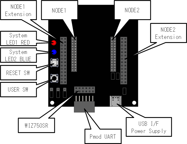
The NEQTO Bridge Connector Board is an evaluation extension board for easily connecting peripheral devices to the peripheral interface of the NEQTO Bridge Module, such as UART, SPI, I2C, and GPIO.
Hereinafter, "NEQTO Bridge Connector Board" is called "connector board" and "NEQTO Bridge Module" is called "module".
For information regarding the "Method for inserting and removing a module", refer here.
Main Specifications
| Item | Specs | Notes |
|---|---|---|
| Digital I/O (3.3V) | UART x 2 ch * SPI x 2 ch I2C x 2 ch GPIO x 13 ch | * By removing the short plug JP4/JP5/JP6, two UARTs are available. |
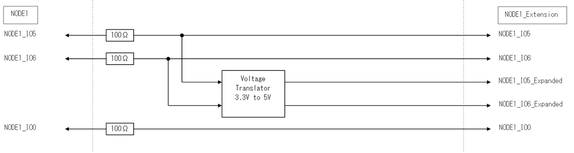
| Digital Output (5V) | GPO x 2 ch | The signal is output with NODE1_IO5 and NODE1_IO6 level shifted to 5V. |
| Photo Coupler Input | 1 ch | Refer to the module specifications. |
| MOS Relay Output | 1 ch | Refer to the module specifications. |
| Analog Input | 2 ch | Refer to the module specifications. |
| Reset SW | 1 ch | |
| User SW | 1 ch | |
| LED | 2 LEDs | System LED1 (Red), System LED2 (Blue) |
| USB | USB 2.0 Full Speed compatible 4.75 V - 5.25 V | - 2 A@5 V recommended - USB Type-C™ compliant connector |
| 3.3V Output | 1 ch | Current Limit: 1A The drive current of this board is included. |
| Operating Temperature Conditions | 0 ℃ - 50 ℃ | |
| Storage Temperature Conditions | 0 ℃ - 50 ℃ | |
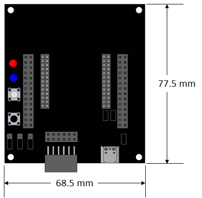
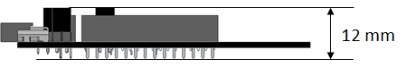
| Size | 68.5 mm x 77.5 mm x 12 mm | Not including protrusions |
External Dimensions
Interfaces
NODE1 Extension / NODE2 Extension
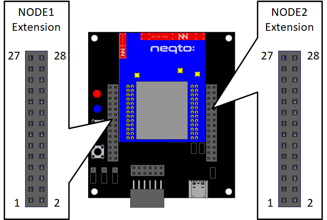
NODE1 Extension
| Signal Name (Extension) | Signal Name (Module) | Pin No. | Signal Name (Module) | Signal Name (Extension) | |
|---|---|---|---|---|---|
| NODE1_IO5_Extension (Output) *3 | - | 27 | 28 | - | NODE1_IO6_Extension (Output) *4 |
| GND | GND | 25 | 26 | GND | GND |
| VDD_RTC (Input) | VDD_RTC | 23 | 24 | GND | GND |
| NRST (Output) *2 | NRST | 21 | 22 | VDD_BATT | VDD_BATT (Output) *1 |
| ANALOG2 (Input) | ANALOG2 | 19 | 20 | VDD_BATT | VDD_BATT (Output) *1 |
| ANALOG1 (Input) | ANALOG1 | 17 | 18 | NODE1 IO6 | NODE1_IO6 (Input / Output) |
| NODE1_IO0 (Input / Output) | NODE1 IO0 | 15 | 16 | NODE1 IO5 | NODE1_IO5 (Input / Output) |
| NODE1_UART_CTS (Input) | NODE1 UART_CTS | 13 | 14 | NODE1 PhotoMOS_IN2 | NODE1_PhotoMOS_IN2 (Input) |
| NODE1_UART_RTS (Output) | NODE1 UART_RTS | 11 | 12 | NODE1 PhotoMOS_IN1 | NODE1_PhotoMOS_IN1 (Input) |
| NODE1_UART_RX (Input) | NODE1 UART_RX | 9 | 10 | NODE1 RELAY_OUT2 | NODE1_RELAY_OUT2 (Output) |
| NODE1_UART_TX (Output) | NODE1 UART_TX | 7 | 8 | NODE1 RELAY_OUT1 | NODE1_RELAY_OUT1 (Output) |
| NODE1_I2C_SCL (Output) | NODE1 I2C_SCL | 5 | 6 | NODE1 I2C_SDA | NODE1_I2C_SDA (Input / Output) |
| NODE1_SPI_MISO (Input) | NODE1 SPI_MISO | 3 | 4 | NODE1 SPI_SCK | NODE1_SPI_SCK (Output) |
| NODE1_SPI_MOSI (Output) | NODE1 SPI_MOSI | 1 | 2 | NODE1 SPI_NCS | NODE1_SPI_NCS (Output) |
- For Pin No.1 - 26, refer to Pinout in the module specifications.
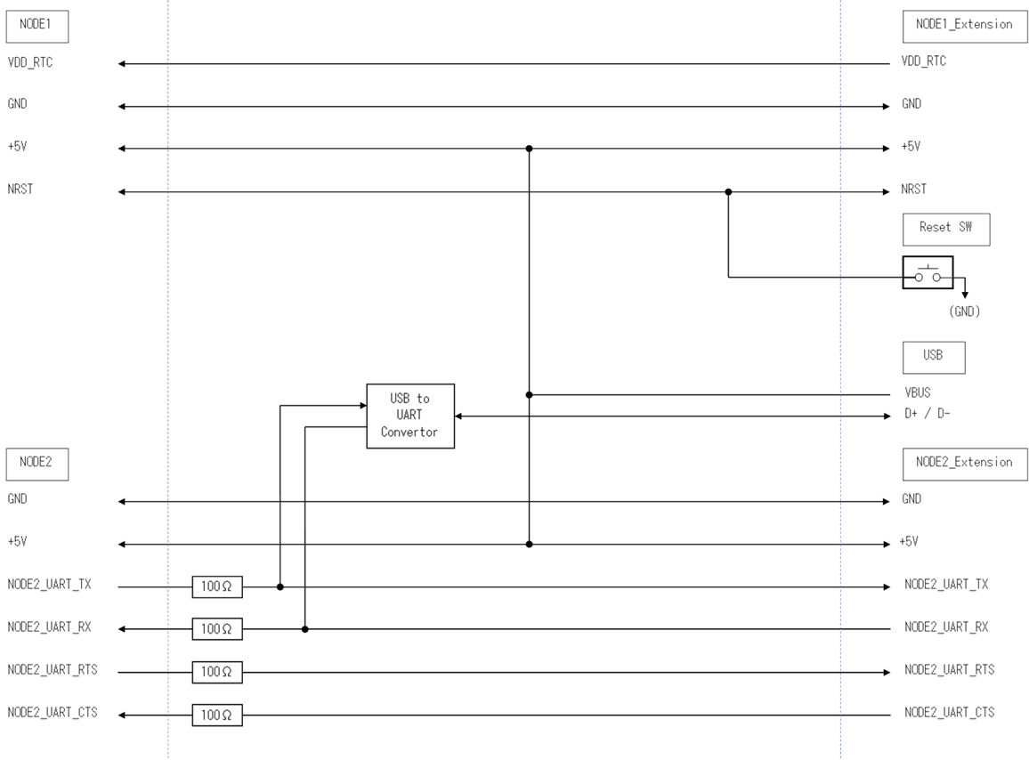
- *1: A 5V USB power supply is output.
- *2: Connected to the RESET SW on the connector board.
- *3: The signal is output with NODE1_IO5 level shifted to 5V.
- *4: The signal is output with NODE1_IO6 level shifted to 5V.
NODE2 Extension
| Signal Name (Extension) | Signal Name (Module) | Pin No. | Signal Name (Module) | Signal Name (Extension) | |
|---|---|---|---|---|---|
| VDD+3.3V (Output) | - | 27 | 28 | - | VDD+3.3V (Output) |
| GND | GND | 25 | 26 | GND | GND |
| VDD_BATT (Output) *6 | VDD_BATT | 23 | 24 | NODE2 IO9 | NODE2_IO9 (Input / Output) |
| USER_SW (Output) *5 | USER_SW | 21 | 22 | NODE2 IO8 | NODE2_IO8 (Input / Output) |
| SYSTEM_LED_RED (Output) *4 | SYSTEM_LED RED | 19 | 20 | NODE2 IO7 | NODE2_IO7 (Input / Output) |
| SYSTEM_LED_BLUE (Output) *3 | SYSTEM_LED BLUE | 17 | 18 | NODE2 IO6 | NODE2_IO6 (Input / Output) |
| NODE2_IO0 (Input / Output) *2 | NODE2 IO0 | 15 | 16 | NODE2 IO5 | NODE2_IO5 (Input / Output) |
| NODE2_UART_CTS (Input) | NODE2 UART_CTS | 13 | 14 | NODE2 IO4 | NODE2_IO4 (Input / Output) |
| NODE2_UART_RTS (Output) | NODE2 UART_RTS | 11 | 12 | NODE2 IO3 | NODE2_IO3 (Input / Output) |
| NODE2_UART_RX (Input) *1 | NODE2 UART_RX | 9 | 10 | NODE2 IO2 | NODE2_IO2 (Input / Output) |
| NODE2_UART_TX (Output) *1 | NODE2 UART_TX | 7 | 8 | NODE2 IO1 | NODE2_IO1 (Input / Output) |
| NODE2_I2C_SCL (Output) | NODE2 I2C_SCL | 5 | 6 | NODE2 I2C_SDA | NODE2_I2C_SDA (Input / Output) |
| NODE2_SPI_MISO (Input) | NODE2 SPI_MISO | 3 | 4 | NODE2 SPI_SCK | NODE2_SPI_SCK (Output) |
| NODE2_SPI_MOSI (Output) | NODE2 SPI_MOSI | 1 | 2 | NODE2 SPI_NCS | NODE2_SPI_NCS (Output) |
- For Pin No.1 - 26, refer to Pinout in the module specifications.
- *1: Depends on the short plug
JP4/JP5/JP6setting. Connected to a USB-UART conversion IC by default. - *2: Connected to the INT signal of the Pmod UART connector if
Pmod Interface Type4 (extension UART)is selected. - *3: Connected to System LED2 (Blue).
- *4: Connected to System LED1 (Red).
- *5: Connected to the USER SW.
- *6: A 5V USB power supply is output.
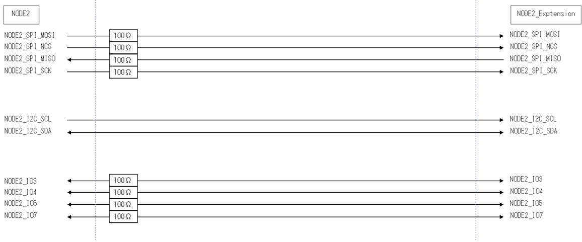
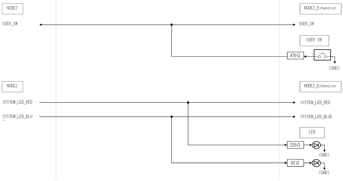
Block diagram
NODE1: SPI / I2C / Relay / Photo Coupler / Analog

NODE1: GPIO
NODE1: Power
NODE2: Power / UART
NODE1: UART
NODE2: Power / UART

NODE2: SPI / I2C / GPIO
NODE2: User Switch / Sysyem LED
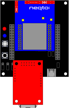
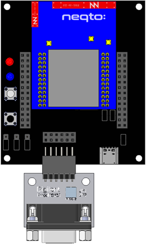
WIZ750SR
This connector is for connecting a WIZnet WIZ750SR.
WIZ750SR is a module that converts serial to ethernet interface.
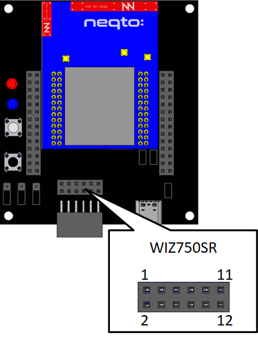
| Pin No. | Signal Name (WIZ750SR) | Signal Name (Module) | Notes |
|---|---|---|---|
| 1 | VCC (Input: 3.3V) | - | 3.3V is supplied from the connector board. |
| 2 | VCC (Input: 3.3V) | - | 3.3V is supplied from the connector board. |
| 3 | U_RXD0 (Input) | NODE1-7 NODE1_UART_TX (Output) | |
| 4 | nRESET (Input) System Reset Signal (0: Active / 1: Normal) | NODE2-22 NODE2_IO8 (Output) | |
| 5 | U_RTS0 (Output) | NODE1-13 NODE1_UART_CTS (Input) | |
| 6 | U_DTR0 / PHY LINK (Output) | Non connection | |
| 7 | U_TXD0 (Output) | NODE1-9 NODE1_UART_RX (Input) | |
| 8 | U_DSR0 / TCP CON / HW_TRIG (Input / Output) | NODE2-8 NODE2_IO1 (Input / Output) | HW_TRIG is not used *1 |
| 9 | U_CTS0 (Input) | NODE1-11 NODE1_UART_RTS (Output) | |
| 10 | NC | Non connection | |
| 11 | GND | - | Connected to GND on the connector board. |
| 12 | GND | - | Connected to GND on the connector board. |
*1: Refer to the WIZ750SR Command Manual.
The prerequisite for the transition to Command mode is that the HW_TRIG signal is not used while the Command mode switch code is used.To prevent the WIZ750SR from automatically connecting to the network before executing the Command mode switch code, add a pull-down resistor of 2KΩ to the HW_TRIG signal.
ex) Connect 2KΩ between NODE2-pin 8 and NODE2-pin 26.
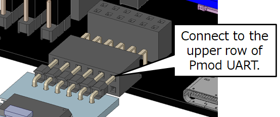
Pmod UART
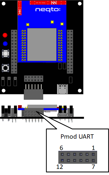
Pmod Interface Type3 (UART)
Pmod UART devices that support Pmod Interface Type 3 (UART) can be connected to the Pmod UART connector.
Pmod Interface Type 3 (UART) compatible devices described in the previous specification "Digilent Pmod™ Interface Specification Revision: November 20, 2011" are applicable.
To use as Pmod Interface Type 3 (UART), the short plug JP1/JP2/JP3 must be set to Type3.
| Pin No. | Signal Name (Pmod UART) | Signal Name (Module) | Notes |
|---|---|---|---|
| 1 | CTS (Input) | NODE1-11 NODE1_UART_RTS (Output) | |
| 2 | RTS (Output) | NODE1-13 NODE1_UART_CTS (Iutput) | |
| 3 | RXD (Output) | NODE1-9 NODE1_UART_RX (Input) | |
| 4 | TXD (Input) | NODE1-7 NODE1_UART_TX (Output) | |
| 5 | GND | - | Connected to GND on the connector board. |
| 6 | VCC (Input) | - | 3.3V is supplied from the connector board. |
Pmod Interface Type4 (UART)
Pmod UART devices that support Pmod Interface Type 4 (UART) can be connected to the Pmod UART connector.
Pmod Interface Type 4 (UART) compatible devices described in the previous specification "Digilent Pmod™ Interface Specification Revision: November 20, 2011" are applicable.
To use as Pmod Interface Type 4 (UART), the short plug JP1/JP2/JP3 must be set to Type4.
| Pin No. | Signal Name (Pmod UART) | Signal Name (Module) | Notes |
|---|---|---|---|
| 1 | CTS (Output) | NODE2-8 NODE2_IO1 (Input / Output) | |
| 2 | TXD (Input) | NODE1-7 NODE1_UART_TX (Output) | |
| 3 | RXD (Output) | NODE1-9 NODE1_UART_RX (Input) | |
| 4 | RTS (Input) | NODE2-10 NODE2_IO2 (Input / Output) | |
| 5 | GND | - | Connected to GND on the connector board. |
| 6 | VCC (Input) | - | 3.3V is supplied from the connector board. |
Pmod Interface Type4 (extension UART)
Pmod UART devices that support Pmod Interface Type 4 (extension UART) can be connected to the Pmod UART connector.
Pmod Interface Type 4 (extension UART) compatible devices described in the previous specification "Digilent Pmod™ Interface Specification Revision: November 20, 2011" are applicable.
To use as Pmod Interface Type 4 (extension UART), the short plug JP1/JP2/JP3 must be set to Type4.
| Pin No. | Signal Name (Pmod UART) | Signal Name (Module) | Notes |
|---|---|---|---|
| 1 | CTS (Output) | NODE2-8 NODE2_IO1 (Input / Output) | |
| 2 | TXD (Input) | NODE1-7 NODE1_UART_TX (Output) | |
| 3 | RXD (Output) | NODE1-9 NODE1_UART_RX (Input) | |
| 4 | RTS (Input) | NODE2-10 NODE2_IO2 (Input / Output) | |
| 5 | GND | - | Connected to GND on the connector board. |
| 6 | VCC (Input) | - | 3.3V is supplied from the connector board. |
| 7 | INT (Output) | NODE2-15 NODE2_IO0 (Input / Output) | |
| 8 | RESET (Input) | NODE2-22 NODE2_IO8 (Input / Output) | |
| 9 | N/S | NODE2-24 NODE2_IO9 (Input / Output) | |
| 10 | N/S | NODE2-18 NODE2_IO6 (Input / Output) | |
| 11 | GND | - | Connected to GND on the connector board. |
| 12 | VCC (Input) | - | 3.3V is supplied from the connector board. |
Pmod RS232C
RS232C communication is possible using a DIGILENT PmodRS232.
PmodRS232 is applicable to Pmod Interface Type 3 (UART) compatible devices described in the previous specification "Digilent Pmod™ Interface Specification Revision: November 20, 2011".
To use as Pmod Interface Type 3 (UART), the short plug JP1/JP2/JP3 must be set to Type3.

| Pin No. | Signal Name (PmodRS232) | Signal Name (Module) | Notes |
|---|---|---|---|
| 1 | CTS (Input) | NODE1-11 NODE1_UART_RTS (Output) | |
| 2 | RTS (Output) | NODE1-13 NODE1_UART_CTS (Input) | |
| 3 | TXD (Output) | NODE1-9 NODE1_UART_RX (Input) | |
| 4 | RXD (Input) | NODE1-7 NODE1_UART_TX (Output) | |
| 5 | GND | - | Connected to GND on the connector board. |
| 6 | VCC (Input) | - | 3.3V is supplied from the connector board. |
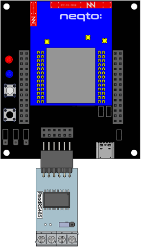
Pmod RS485
RS485 communication is possible using a DIGILENT PmodRS485.
PmodRS485 is applicable to Pmod Interface Type 4 (UART) compatible devices described in the previous specification "Digilent Pmod™ Interface Specification Revision: November 20, 2011".
To use as Pmod Interface Type 4 (UART), the short plug JP1/JP2/JP3 must be set to Type4.
| Pin No. | Signal Name (PmodRS485) | Signal Name (Module) | Notes |
|---|---|---|---|
| 1 | ~RE (Input) Receive Enable (0: Enable / 1: Disable) | NODE2-8 NODE2_IO1 (Output) | |
| 2 | TxD (Input) | NODE1-7 NODE1_UART_TX (Output) | |
| 3 | RxD (Output) | NODE1-9 NODE1_UART_RX (Input) | |
| 4 | DE (Input) Drive Enable (0: Disable / 1: Enable) | NODE2-10 NODE2_IO2 (Output) | |
| 5 | GND | - | Connected to GND on the connector board. |
| 6 | VCC (Input) | - | 3.3V is supplied from the connector board. |
Short Plug
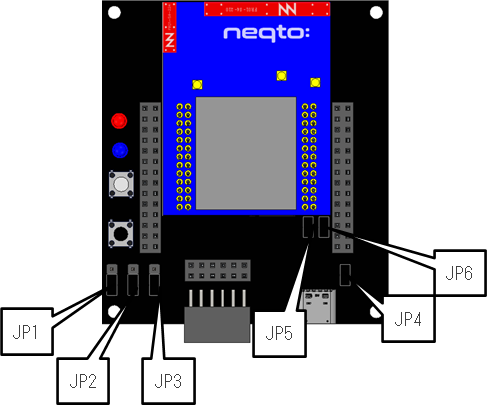
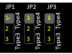
JP1 / JP2 / JP3
To use Pmod UART devices that support Pmod Interface Type 3 (UART), Pmod Interface Type 4 (UART), and Pmod Interface Type 4 (extension UART), the following short plug settings are required.
To use as Pmod Interface Type 3 (UART), connect the short plug JP1/JP2/JP3 to Type3 side.
To use as Pmod Interface Type 4 (UART) or Pmod Interface Type 4 (extension UART), connect the short plug JP1/JP2/JP3 to Type4 side.
The following is an example of the Type3 setting:
| JP No. | Configuration |
|---|---|
| JP1 JP2 JP3 | 1-2: Type4 To use a device that supports Pmod Interface Type4 (UART) or Pmod Interface Type4 (extension UART) 2-3: Type3 (default)To use a device that supports Pmod Interface Type3 (UART) |
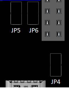
JP4 / JP5 / JP6
The connector board is mounted with a USB-UART conversion IC, which enables USB data communication.
If USB data communication is not to be used, or if the module's NODE2_UART is intended to be used, the USB-UART converter IC can be isolated from the circuit by removing the short plug JP4/JP5/JP6.
| JP No. | Configuration |
|---|---|
| JP4 | Open: Does not connect the power supply terminal of USB-UART conversion IC and VBUS. Close: Connects the power supply terminal of USB-UART conversion IC and VBUS. (default) |
| JP5 | Open: Does not connect the TXD of the USB-UART converter IC and the NODE2_UART_RX of the module. Close: Connects the TXD of the USB-UART converter IC and the NODE2_UART_RX of the module. (default) |
| JP6 | Open: Does not connect the RXD of the USB-UART converter IC and the NODE2_UART_TX of the module. Close: Connects the RXD of the USB-UART converter IC and the NODE2_UART_TX of the module. (default) |
Connector List
| Function | Address | Parts Number | Maker |
|---|---|---|---|
| Pmod UART | - | FSR-42085-06 | Hirosugi Keiki |
| WIZ750SR | - | FSR-42085-06 | Hirosugi Keiki |
| USB | - | CX90B1-24P | Hirose Electric |
| NEQTO Bridge Module | Node1, Node2 | FSS-22043-13 | Hirosugi Keiki |
| Extension | Node1, Node2 | FSS-42085-14 | Hirosugi Keiki |
Method for inserting and removing a module
Ensure that the following steps are performed with the power off.
Inserting a module
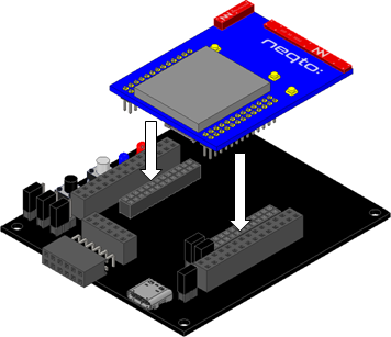
Insert the module into the connector board.
Align the module pins with the connector board pin sockets ensuring that there is no misalignment, and push both edges of the module with equal force.
Before turning on the power, check once again for misalignment of the pins.
Removing a module
Remove the module from the connector board.
The module and the connector board are firmly connected by pin sockets.
While holding down the connector board, slowly and gradually move the module up and down, lifting it up to remove it from the pin sockets. Please note that the pins may be bent if removed forcibly.