01. About STM32 Discovery Kit (B-L4S5I-IOT01A)
Overview
The NEQTO Engine installed on the STMicroelectronics B-L4S5I-IOT01A Discovery Kit makes it easy to connect to NEQTO Console and the customer's cloud environment. It also allows customers to easily control sensors and devices via physical interfaces.
System Configuration
| Top view |
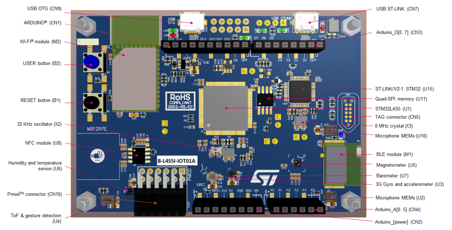 |
| Bottom view |
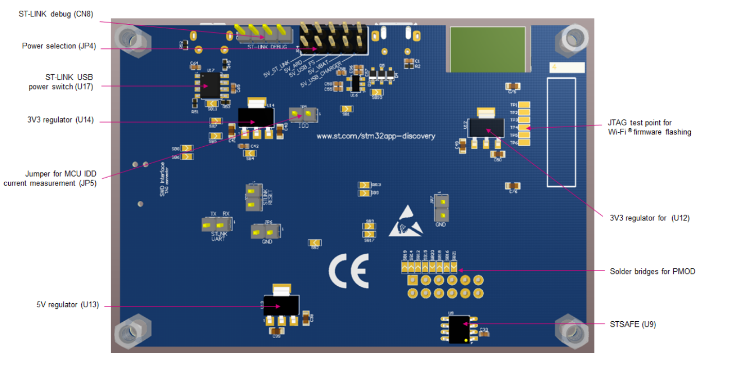 |
Peripheral support list
The peripherals that the NEQTO Engine supports are as follows:
| Item | Model Name | Supported | Notes |
|---|---|---|---|
| Micro-B USB connector | ✓ | ST-LINK USB connector | |
| Micro-AB USB connector | - | USB_OTG_FS connector Available as a power input only. | |
| Pmod™ (2A) connector Pmod™ (4A) connector | ✓ | Type 2A and Type 4A described in "Digilent Pmod™ Interface Specification Revision: November 20, 2011" are available. | |
| ARDUINO® Uno Shield connector | ✓ | Refer to Pinout for the available neqto.js interface. | |
| Wi-Fi® module | ISM43362-M3G-L44 | ✓ | System controlled |
| Bluetooth® 4.1 module | ST SPBTLE-RF | - | |
| Sub-GHz (Spirit) module | SPSGRF | - | Not fitted |
| NFC module | ST25DV04K | ✓ | User controlled (I2C(2)) |
| 3-axis magnetometer | LIS3MDL | ✓ | User controlled (I2C(2)) |
| 3D gyroscope | LSM6DSL | ✓ | User controlled (I2C(2)) |
| Digital barometer | LPS22HB | ✓ | User controlled (I2C(2)) |
| Humidity and temperature | HTS221 | ✓ | User controlled (I2C(2)) |
| ToF and gesture detection | VL53L0X | ✓ | User controlled (I2C(2)) |
| Authentication and security | STSAFE-A110 | ✓ | User controlled (I2C(2)) |
| Digital microphone | MP34DT01 | - | |
| Tag connector | - | ||
| Quad-SPI NOR Flash memory | MX25R6435F | ✓ | System controlled |
| LED LD1 | - | On depending on SPI(1)_SCK signal level | |
| LED LD2 | ✓ | User controlled (GPIO(24)_LED2) | |
| LED LD3 | - | Always off | |
| LED LD4 | ✓ | System controlled (SYSTEM_LED BLUE) | |
| LED LD5 | - | Always on | |
| LED LD6 | - | Refer to "4.3 ST-LINK/V2 status LED" here for details. | |
| LED LD7 | - | Refer to "4.3.4 FAULT pin" here for details. | |
| LED LD8 | ✓ | System controlled (SYSTEM_LED RED) | |
| LED LD9 | - | Always on if power is supplied from USB_OTG_FS. | |
| User button | ✓ | User controlled (UserSW) Used to activate User Console Mode. | |
| Reset button | ✓ | User controlled (NRST) |
Main Specifications
| Item | Specifications | Notes | ||
|---|---|---|---|---|
| CPU | STM32L4S5VIT6 (ARM® Cortex®-M4F ROM 2MB / RAM 640KB) | |||
| Flash memory (External memory) | 64 MBit (8 MByte) | |||
| Digital I/O |
UART x 2 ch (or 3 ch) *
SPI x 2 ch (or 1 ch) * I2C x 2 ch GPIO x 23 ch GPIO (PWM capable) x 5 ch GPIO (LED) x 1 ch NRST (Reset button) USER_SW (User button) SYSTEM_LED_BLUE SYSTEM_LED_RED |
|||
| Digital I/O Voltage | 3.3 V | |||
| Analog Input | ADC x 2 ch | |||
| Communication Interface | IEEE802.11b/g/n 2.4GHz band | For more information, refer here. | ||
| Main Power Supply | 5 V | For more information, refer to "6.2 Power supply" here. | ||
| Operating Conditions | Temperature: -40 ℃ - 85 ℃ | |||
- Either SPI x 1ch or UART x 1ch can be used. For details, please refer to Pinout *3.
Pinout
The neqto.js interface that can be used with B-L4S5I-IOT01A is as follows:
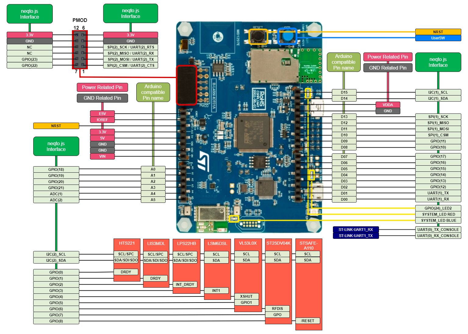
neqto.js Interfaces
The following is a comparison table of the B-L4S5I-IOT01A Pin List and the neqto.js interface:
The colored cells indicate the user interfaces that can be controlled from neqto.js.
| Connector Pin Number | Pin Name | STM32L4+ Pin | neqto.js Interfaces | Notes | |
|---|---|---|---|---|---|
| CN2-1 | E5V | - | - | ||
| CN2-2 | IOREF | - | - | ||
| CN2-3 | NRST | NRST | - | ||
| CN2-4 | 3.3V | - | - | ||
| CN2-5 | 5V | - | - | ||
| CN2-6 | GND | - | - | ||
| CN2-7 | GND | - | - | ||
| CN2-8 | VIN | - | - | ||
| CN4-1 | ARD.A0-ADC | PC5 | GPIO(18) | INT WAKEUP | |
| CN4-2 | ARD.A1-ADC | PC4 | GPIO(19) | ||
| CN4-3 | ARD.A2-ADC | PC3 | GPIO(20) | ||
| CN4-4 | ARD.A3-ADC | PC2 | GPIO(21) | ||
| CN4-5 | ARD.A4-ADC | PC1 | ADC(1) | ||
| CN4-6 | ARD.A5-ADC | PC0 | ADC(2) | ||
| CN1-10 | ARD.D15-I2C1_SCL | PB8 | I2C(1)_SCL | ||
| CN1-9 | ARD.D14-I2C1_SDA | PB9 | I2C(1)_SDA | ||
| CN1-8 | VDDA | - | - | ||
| CN1-7 | GND | - | - | ||
| CN1-6 | ARD.D13-SPI1_SCK / LED1 | PA5 | SPI(1)_SCK | ||
| CN1-5 | ARD.D12-SPI1_MISO | PA6 | SPI(1)_MISO | ||
| CN1-4 | ARD.D11-SPI1_MOSI / PWM | PA7 | SPI(1)_MOSI | ||
| CN1-3 | ARD.D10-SPI_SSN / PWM | PA2 | SPI(1)_NCS | ||
| CN1-2 | ARD.D9-PWM | PA15 | GPIO(11) | PWM *1 | |
| CN1-1 | ARD.D8 | PB2 | GPIO(10) | ||
| CN3-8 | ARD.D7 | PA4 | GPIO(17) | ||
| CN3-7 | ARD.D6-PWM | PB1 | GPIO(16) | PWM *2 | |
| CN3-6 | ARD.D5-PWM | PB4 | GPIO(15) | PWM *2 | |
| CN3-5 | ARD.D4 | PA3 | GPIO(14) | PWM *1 INT | |
| CN3-4 | ARD.D3-PWM / INT1_EXTI0 | PB0 | GPIO(13) | PWM *2 INT | |
| CN3-3 | ARD.D2-INT0_EXTI14 | PD14 | GPIO(12) | INT | |
| CN3-2 | ARD.D1-UART4_TX | PA0 | UART(1)_TX | ||
| CN3-1 | ARD.D0-UART4_RX | PA1 | UART(1)_RX | ||
| Pmod-1 | Pmod-UART2_Tx/ SPI2_CSN | PD5/PD3 | SPI(2)_NCS | UART(2)_CTS | *3 |
| Pmod-2 | Pmod-UART2_RTS/ SPI2_MOSI | PD4/PD5 | SPI(2)_MOSI | UART(2)_TX | *3 |
| Pmod-3 | Pmod-UART2_CTS/ SPI2_MISO | PD3/PD6 | SPI(2)_MIS0 | UART(2)_RX | *3 |
| Pmod-4 | PmodSPI2_SCK | PD1/PD4 | SPI(2)_SCK | UART(2)_RTS | *3 |
| Pmod-5 | GND | - | - | ||
| Pmod-6 | 3.3V | - | - | ||
| Pmod-7 | Pmod-IRQ_EXTI2 | PD2 | GPIO(22) | INT | |
| Pmod-8 | Pmod-RESET | PD0 | GPIO(23) | ||
| Pmod-9 | NC | NC | - | ||
| Pmod-10 | NC | NC | - | ||
| Pmod-11 | GND | - | - | ||
| Pmod-12 | 3.3V | - | - | ||
| - | INTERNAL-I2C2_SCL | PB10 | I2C(2)_SCL | *4 | |
| - | INTERNAL-I2C2_SDA | PB11 | I2C(2)_SDA | *4 | |
| - | HTS221_DRDY_EXTI15 | PD15 | GPIO(0) | INT | |
| - | LIS3MDL_DRDY_EXTI8 | PC8 | GPIO(1) | INT | |
| - | LPS22HB_INT_DRDY_EXTI10 | PD10 | GPIO(2) | INT | |
| - | LSM6DSL_INT1_EXTI11 | PD11 | GPIO(3) | INT | |
| - | VL53L0X_XSHUT | PC6 | GPIO(4) | ||
| - | VL53L0X_GPIO1_EXTI7 | PC7 | GPIO(5) | INT | |
| - | ST25DV04K RF_DISABLE | PE2 | GPIO(6) | ||
| - | ST25DV04K-GPO | PE4 | GPIO(7) | INT | |
| - | STSAFE-A110-RESET | PD7 | GPIO(8) | ||
| Micro-B USB connector | ST-LINK-UART1_TX | PB6 | UART(0)_TX_CONSOLE | ||
| Micro-B USB connector | ST-LINK-UART1_RX | PB7 | UART(0)_RX_CONSOLE | ||
| - | LED2 | PB14 | GPIO(24)_LED2 | *5 | |
| - | USB_OTG_OVRCR_EXTI3 | PE3 | SYSTEM_LED RED | ||
| - | LED3 (Wi‑Fi®) & LED4 (BLE) | PC9 | SYSTEM_LED BLUE | ||
| User button | BUTTON_EXTI13 | PC13 | UserSW | WAKEUP | |
| Reset button | STM_NRST | NRST | NRST | ||
- *1: When using PWM output with GPIO(11) or GPIO(14), the time resolution is in units of 1us.
- *2: When using PWM output with GPIO(13), GPIO(15), or GPIO(16), the time resolution is in units of 100us.
- *3: The default selected state of the of the Pmod connector is
Type 2A (SPI). To utilizeType 4A (UART), hardware modifications must be made. Refer to "Table 12. Pmod™ solder bridge configuration" here for details.
The neqto.js interface supports both SPI(2) and UART(2), however either interface is available exclusively. - *4: Refer to "6.13 I2C addresses of modules used on MB1297" here for slave addresses of the I2C modules.
- *5: Only GPIO operation mode 5 (OUT/PUSH-PULL) can be used.
External Dimensions
| Item | Specifications | Notes |
|---|---|---|
| B-L4S5I-IOT01A | 90 mm x 62 mm | Refer to "Figure 5." here for more details. |
Interface Specifications
Supported Baudrates
| Item | Specs | Notes |
|---|---|---|
| UART(0)_Console Baudrate | 2,400 bits/s - 921,600 bits/s In case of User Console Mode, Baud rate is fixed 921,600 bits/s and uses UART(0)_Console. | |
| UART(1) Baudrate | 2,400 bits/s - 921,600 bits/s | |
| UART(2) Baudrate | 2,400 bits/s - 921,600 bits/s | |
| SPI(1) Baudrate | 0.15625M bits/s - 20M bits/s | |
| SPI(2) Baudrate | 0.15625M bits/s - 20M bits/s | |
| I2C(1) Baudrate | 100k bits/s, 400k bits/s | |
| I2C(2) Baudrate | 100k bits/s, 400k bits/s |
Pin Initial Values
| Function | neqto.js Interfaces | Initial value | Notes |
|---|---|---|---|
| UART | UART(0)_TX_CONSOLE | Default High | |
| UART(0)_RX_CONSOLE | Internal PULL-UP | ||
| UART | UART(1)_TX | Default High | |
| UART(1)_RX | Internal PULL-UP | ||
| UART | UART(2)_TX | Default High | |
| UART(2)_RX | Internal PULL-UP | ||
| UART(2)_RTS | Default High | ||
| UART(2)_CTS | Internal PULL-UP | ||
| SPI | SPI(1)_SCK | External PULL-DOWN 200.0 Ω | |
| SPI(1)_MISO | Internal PULL-UP | ||
| SPI(1)_MOSI | Internal PULL-UP | ||
| SPI(1)_NCS | Internal PULL-UP | ||
| SPI | SPI(2)_NCS | Internal PULL-UP | |
| SPI(2)_MOSI | Internal PULL-UP | ||
| SPI(2)_MISO | Internal PULL-UP | ||
| SPI(2)_SCK | Internal PULL-UP | ||
| I2C | I2C(1)_SCL | External PULL-UP 2.2 kΩ | |
| I2C(1)_SDA | External PULL-UP 2.2 kΩ | ||
| I2C | I2C(2)_SCL | External PULL-UP 2.2 kΩ | |
| I2C(2)_SDA | External PULL-UP 2.2 kΩ | ||
| GPIO | GPIO(0) | GPIO operation mode: 2 (IN) | |
| GPIO(1) | GPIO operation mode: 2 (IN) | ||
| GPIO(2) | GPIO operation mode: 2 (IN) | ||
| GPIO(3) | GPIO operation mode: 2 (IN) | ||
| GPIO(4) | GPIO operation mode: 2 (IN) External PULL-UP 10.0 kΩ | ||
| GPIO(5) | GPIO operation mode: 2 (IN) External PULL-UP 10.0 kΩ | ||
| GPIO(6) | GPIO operation mode: 2 (IN) External PULL-DOWN 30.0 kΩ | ||
| GPIO(7) | GPIO operation mode: 2 (IN) External PULL-UP 10.0 kΩ | ||
| GPIO(8) | GPIO operation mode: 2 (IN) | ||
| GPIO(10) | GPIO operation mode: 0 (IN/PULL-UP) | ||
| GPIO(11) | GPIO operation mode: 0 (IN/PULL-UP) | ||
| GPIO(12) | GPIO operation mode: 0 (IN/PULL-UP) | ||
| GPIO(13) | GPIO operation mode: 0 (IN/PULL-UP) | ||
| GPIO(14) | GPIO operation mode: 0 (IN/PULL-UP) | ||
| GPIO(15) | GPIO operation mode: 0 (IN/PULL-UP) | ||
| GPIO(16) | GPIO operation mode: 0 (IN/PULL-UP) | ||
| GPIO(17) | GPIO operation mode: 0 (IN/PULL-UP) | ||
| GPIO(18) | GPIO operation mode: 0 (IN/PULL-UP) | ||
| GPIO(19) | GPIO operation mode: 0 (IN/PULL-UP) | ||
| GPIO(20) | GPIO operation mode: 0 (IN/PULL-UP) | ||
| GPIO(21) | GPIO operation mode: 0 (IN/PULL-UP) | ||
| GPIO(22) | GPIO operation mode: 0 (IN/PULL-UP) | ||
| GPIO(23) | GPIO operation mode: 0 (IN/PULL-UP) | ||
| GPIO(24)_LED2 | GPIO operation mode: 5 (OUT/PUSH-PULL) | ||
| Reset Input | NRST | Internal PULL-UP | Low: Reset High: Normal (Default) * To reset, hold Low for 1 ms or more. |
| User Switch Input | UserSW | External PULL-UP 10.0 kΩ | Low: ON High: OFF (Default) |
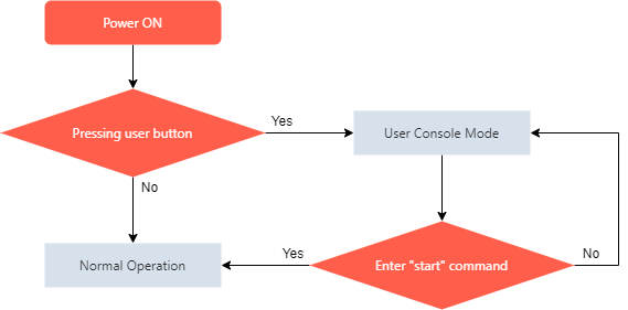
About User Console Mode
The User Console Mode provides a command console interface using the UART interface.
It is available for inputting various settings commands and displaying real-time logs.
When the power is turned on while the user button (blue button) is pushed, the User Console mode is activated.