03. NEQTO Bridge LTE Module Initial Setup
Introduction
NEQTO Bridge LTE Module is available in two types: NEQTO Bridge LTE-1 Module and NEQTO Bridge LTE-M/NB Module. The procedure is equivalent.
Hereinafter, "NEQTO Bridge device" is called "device", and "NEQTO Bridge LTE Module" is called "module". "NEQTO Bridge IO Board" or "NEQTO Bridge Digital IO Board" is called "IO board".
The following describes the procedure when using the module and the IO board.
Before beginning the initial setup, please review the supported communication specifications:
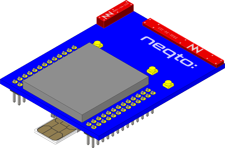
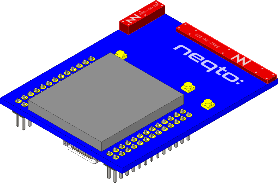
Insertion of USIM Card
Before the initial setup, a USIM card must be inserted into the module.
With the power off, push the USIM card into the USIM slot until it locks.
For information regarding the method for inserting a module into an IO board and removing a module from an IO board, refer here.
Initial Setup
To perform the initial setup, follow the steps below:
Prepare a Windows PC with TeraTerm (Terminal software) installed in advance, and start the module in User Console mode.
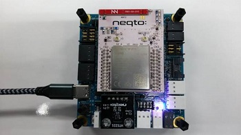
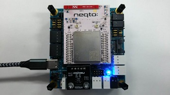
While pressing the User SW on the IO board, connect the device and PC via USB.
Use the USB cable for communication.The device's red and blue system LEDs will turn on at the same time.
If the two LEDs do not turn on, disconnect the USB from the PC and repeat from step 1.
Start TeraTerm and open the COM port.
When the USB is connected to a PC for the first time, the FTDI USB serial conversion driver is automatically installed and a COM port is created.
If the driver is not installed automatically, download the VCP driver for Windows from here and install it.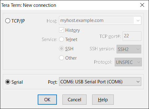
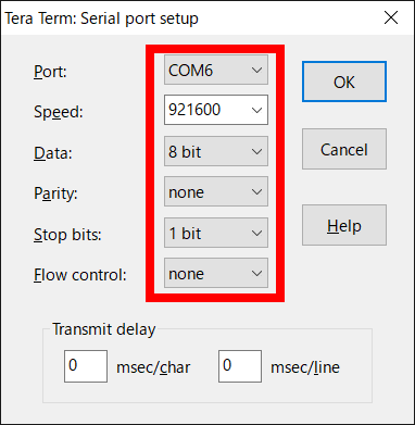
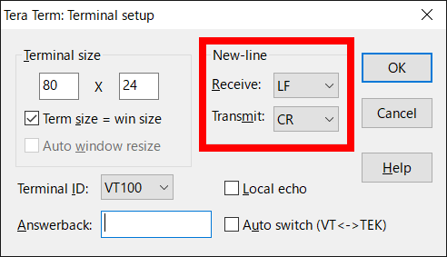
Set the serial port and termial settings as shown below.
The User Console mode will start up, and a prompt will appear when the enter key is pressed.
If no prompt appears, disconnect the USB from the PC and repeat from step 1.
> ↵
> ↵
>
Configure the communication settings for the device.
Set the required configurations using the commands below.
The set value will be immediately saved in the nonvolatile memory after the command is input.List of communication setting commands
Command Content Note lte set apn <APN> Sets the APN.
A maximum of 62 single-byte alphanumeric characters, and{.}and{-}symbols, can be used.
If <APN> is omitted the setting value will be blank.lte set user <USER> Sets the user name.
A maximum of 62 single-byte alphanumeric characters and single-byte symbols can be used. (May not contain{space}or special characters.)
If <USER> is omitted the setting value will be blank.lte set pass <PASS> Sets the password.
A maximum of 62 single-byte alphanumeric characters and single-byte symbols can be used. (May not contain{space}or special characters.)
If <PASS> is omitted the setting value will be blank.lte get Gets the LTE connection setting information (APN, user name, password).
If a setting value is blank, nothing is set.The following are example command inputs:
> lte set apn lte.com↵
OK
> lte set user user↵
OK
> lte set pass abcdefg↵
OK
> lte get↵
APN : lte.com
USERNAME : user
PASSWORD : abcdefg
>
For APN, user name, and password information related to USIM, please contact the telecommunications carrier.
Enter the
startcommand to launch the NEQTO service.
Note that node registration must be completed on the NEQTO Console before entering thestartcommand.Command Content Note start Establish a communication connection and launch the NEQTO service. > start↵
OK
> [system][info]Certification Complete(00.00.00)
[system][info]Checking Script...
[system][info]Ready
Thu Apr 08 2021 02:31:03 GMT+00:00+766ms : Hello World!!! 0
Thu Apr 08 2021 02:31:04 GMT+00:00+766ms : Hello World!!! 1
Thu Apr 08 2021 02:31:05 GMT+00:00+766ms : Hello World!!! 2
Thu Apr 08 2021 02:31:06 GMT+00:00+766ms : Hello World!!! 3
Thu Apr 08 2021 02:31:07 GMT+00:00+766ms : Hello World!!! 4
Thu Apr 08 2021 02:31:08 GMT+00:00+766ms : Hello World!!! 5
Thu Apr 08 2021 02:31:09 GMT+00:00+766ms : Hello World!!! 6
Thu Apr 08 2021 02:31:10 GMT+00:00+766ms : Hello World!!! 7
Thu Apr 08 2021 02:31:11 GMT+00:00+766ms : Hello World!!! 8
Thu Apr 08 2021 02:31:12 GMT+00:00+766ms : Hello World!!! 9
Thu Apr 08 2021 02:31:13 GMT+00:00+766ms : Hello World!!! 10
Troubleshooting
The operating status of the device can be ascertained from the state of the system LEDs and the display of event messages.
While System LED Red remains on and System LED Blue flashes continuously, the NEQTO service does not start.
Cannot connect to LTE.
» Review the LTE communication settings of Spresense.
» Verify that the USIM card is inserted correctly.
» Verify that the LTE wireless communication environment is favorable.While System LED Red remains off and System LED Blue flashes continuously, the NEQTO service does not start.
Cannot connect to NEQTO Console.
» Review the device settings on the NEQTO Console.
» If the issue cannot be resolved, please contact NEQTO support for further assistance.
Appendix
Get Device-specific Information
The following commands may be used to get device-specific information.
| Command | Content | Note |
|---|---|---|
| sr | Gets the serial ID of the device. | |
| v | Gets the firmware version of the device. |
Antenna Level Indication
The current antenna level may be indicated via the system LED.
Refer to System LED Indications for the LED display pattern.
Supported from FW version 00.00.28 or later.
| Command | Content | Note |
|---|---|---|
| lte led <on/off> | Sets the antenna level indicator. off: Disabled on: Indicate the antenna level via LED. The default value is off. |
LTE Category Settings
The following command may be used to set the LTE category.
Available only for the NEQTO Bridge LTE-M/NB Module.
The set value is immediately saved in the nonvolatile memory after the command is input.
Supported from FW version 01.01.00 or later.
| Command | Content | Note |
|---|---|---|
| lteex set cat <0/1> | Sets the LTE category. 0: Category M1 1: Category NB1 The default value is 0. | |
| lteex get cat | Gets the LTE category settings. |
Roaming Settings
The following command may be used to enable roaming communication.
The set value is immediately saved in the nonvolatile memory after the command is input.
Supported from FW version 00.00.27 or later.
| Command | Content | Note |
|---|---|---|
| lteex set roaming <0/1> | Enables/Disables roaming. 0: Disabled 1: Enabled The default value is 0. | |
| lteex get roaming | Gets the roaming settings. |
Out-of-Service Watchdog Timer
This timer is started when out-of-service is detected and stopped when within-service is detected.
If the out-of-service condition persists and a timeout occurs, the LTE modem will be restart while the operation script continues execution.
This feature is a safeguard function that will attempt to recover from continuous loss of communication due to unexpected LTE modem failure.
The set value is immediately saved in the nonvolatile memory after the command is input.
Supported from FW version 00.00.25 or later.
| Command | Content | Note |
|---|---|---|
| lteex set ooswatchdog <TIMER> | Sets the out-of-service watchdog timer. <TIMER>: 0 - 24 [hour] If 0 is specified, it will be disabled. The default value is 0. | |
| lteex get ooswatchdog | Gets the out-of-service watchdog timer settings. |
Get Identification Information
The following command may be used to get the LTE identification information of the LTE module.
Note that if this command is executed before the start command or during the initialization process after the start command, the identification information will be blank.
Supported from FW version 01.00.00 or later.
| Command | Content | Note |
|---|---|---|
| lte id | Gets the identification information of the LTE module. IMEI:IMEI (International Mobile Equipment Identity) It will be a 15-digit character string. IMSI:IMSI (International Mobile Subscriber Identity) It will be a 15-digit character string. If SIM is not detected, it will be blank. MSISDN:MSISDN (Mobile Station International Subscriber Directory Number) If SIM is not detected, it will be blank. ICCID: ICCID (IC Card ID) It will be a 19-20 digit character string. If SIM is not detected, it will be blank. MODEL: LTE module model name 'BG96', 'SIMCOM_SIM7500JC'REVISION: LTE module firmware revision (FW version 02.00.01 or later) If the module is not started, it will be blank. |
Signal Quality Information Acquisition
The following command may be used to get the LTE signal quality information.
Note that if this command is executed before the start command or during the initialization process after the start command, the acquisition will fail.
Supported from FW version 01.00.00 or later.
| Command | Content | Note |
|---|---|---|
| lte sq | Gets the LTE signal quality information. TIME:Updated date and time (Unixtime) REGISTERED:Registration status of the serving cell 0: not registered 1: registered If acquisition fails, it will be 0. RSSI:RSSI[dBm] Range: -113 - -51 -255: Unknown If acquisition fails, it will be -255. RSRP:RSRP[dBm] Range: -141 - -44 -255: Unknown If acquisition fails, it will be -255. RSRQ:RSRQ[dB] Range: -20 - -3 -255: Unknown If acquisition fails, it will be -255. SINR:SINR[dB] Range: -20 - 30 -21: Unknown If acquisition fails, it will be -21. TAC:TAC (Tracking Area Code) If acquisition fails, it will be 0. CI:CI (Cell ID) If acquisition fails, it will be 0. MCC:MCC (Mobile Country Code) If acquisition fails, it will be 0. MNC:MNC (Mobile Network Code) If acquisition fails, it will be 0. |
Extension Board Settings
The following command may be used to configure the settings related to the "NEQTO Bridge IO Board" and "NEQTO Bridge Digital IO Board" controls.
The set value is immediately saved in the nonvolatile memory after the command is input.
Supported from FW version 01.05.00 or later.
| Command | Content | Note |
|---|---|---|
| exbc set conf <0/1> | Sets the IO Board Automatic Detection. 0: Enabled 1: Disabled The default value is 0. Since FW version 02.00.00, if the result of auto-detection is non-detection, it voluntarily becomes disabled. | |
| exbc get | Displays a list of extension board setting values. |
Factory Reset
The following commands may be used to restore the device factory settings.
All communication settings and storage data will be reset.
Supported from FW version 01.05.00 or later.
| Command | Content | Note |
|---|---|---|
| frst <serialId> | Performs factory reset. For serialId, specify the serial ID (which can be obtained using the sr command).After executing the command, wait until a response is returned. It takes about 10 seconds. | |
| frst <serialId> full | Performs a complete factory reset. The storage will be completely erased. For serialId, specify the serial ID (which can be obtained using the sr command).After executing the command, wait until a response is returned. It takes about 60 seconds. |