14. SPI
The SPI object is a built-in object that provides SPI communication functions.
Functional overview:
- Provides SPI master mode function.
Limitations:
- The write and read methods of the SPI instance are block processing.
In particular, if you read or write a large amount of data at one time with a low communication speed setting, a long block time will occur until the communication is completed, so please take it into consideration.
Abstracts
| Methods()/Properties | Summary | Version | Note |
|---|---|---|---|
| new SPI() | Creates an SPI instance. | 01.04.00+ |
{SPI} Instance
| Methods()/Properties | Summary | Version | Note |
|---|---|---|---|
| .open() | Starts the communication. | 01.04.00+ | |
| .close() | Ends the communication. | 01.04.00+ | |
| .write() | Writes the data. | 01.04.00+ | |
| .read() | Reads the data. | 01.04.00+ | |
| .writeRead() | Reads the data after writing the data. | 01.04.00+ | |
| .writeReadFullDup() | Writes data and reads data at the same time. (Full-duplex communication) | 01.04.00+ | |
| .readAndCompare() | Repeats reading data until the specified target value is read. | 01.04.00+ | |
| .setChipSelect() | Manually controls the chip select signal. | 01.04.00+ |
Details
new SPI(nodeNo)
Creates an SPI instance.
| Name | Type | M/O | Summary | Note |
|---|---|---|---|---|
| nodeNo | number | mandatory | Specifies the node number of the SPI interface to be used. Please refer to Pinout. | |
| return | {SPI} | - | {SPI} : Generated {SPI} |
.open(baudrate,clkmode,bitorder,csmode)
Starts the communication.
| Name | Type | M/O | Summary | Note |
|---|---|---|---|---|
| baudrate | number | mandatory | Communication speed 0: 20Mbps 1: 10Mbps 2: 5Mbps 3: 2.5Mbps 4: 1.25Mbps 5: 0.625Mbps 6: 0.3125Mbps 7: 0.15625Mbps | |
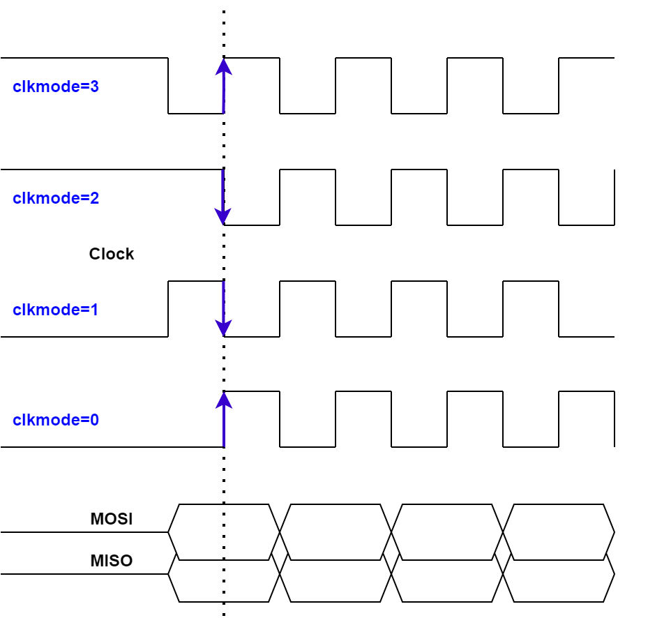
| clkmode | number | mandatory | Clock mode 0: Low level when idle, Rising edge sampling 1: Low level when idle, Falling edge sampling 2: High level when idle, Falling edge sampling 3: High level when idle, Rising edge sampling Please refer to Clock mode details. | |
| bitorder | number | mandatory | Bit order 0: MSB first 1: LSB first | |
| csmode | number | mandatory | Chip select mode 0: Automatic (Automatically controlled to High level when idle and Low level when active. Set to the Low level while each write and read method is being executed.) 1: Manual (Use .setChipSelect() to control the chip select signal. Note that when the SPI is opened and closed, the High level is forcibly set.) | |
| return | boolean | - | true: Success false: Failure |
Clock mode details
.close()
Ends the communication.
| Name | Type | M/O | Summary | Note |
|---|---|---|---|---|
| return | boolean | - | true: Success false: Failure |
.write(buff)
Writes the data.
| Name | Type | M/O | Summary | Note |
|---|---|---|---|---|
| buff | ArrayBuffer | mandatory | Write data The data size that can be specified is 1 to 4096 bytes. | ArrayBuffer size will be written. |
| return | boolean | - | true: Success false: Failure | If the parameter is abnormal, an exception is raised. |
When the data length is 1 byte, use Uint8Array as follows:
var buff = new ArrayBuffer(1);
var arr = new Uint8Array(buff);
arr[0] = your_data;
var ret = spi.write(buff);
.read(len[,dummyData])
Reads the data.
| Name | Type | M/O | Summary | Note |
|---|---|---|---|---|
| len | number | mandatory | Specify the read data length. Range: 1 - 4096 | |
| dummyData | number | optional | Specify the dummy data to be sent when reading. Range: 0x00 - 0xFF The default value is 0xFF. | |
| return | Arraybuffer | - | Read data If read function fails, the returned size will be 0. | If the parameter is abnormal, an exception is raised. |
.writeRead(buff,len[,dummyData])
Reads the data after writing the data.
If chip select mode is set to automatic, the chip select signal holds the Low level from the start of writing to the end of reading.
| Name | Type | M/O | Summary | Note |
|---|---|---|---|---|
| buff | ArrayBuffer | mandatory | Write data The data size that can be specified is 1 to 4096 bytes. | ArrayBuffer size will be written. |
| len | number | mandatory | Specify the read data length. Range: 1 - 4096 | |
| dummyData | number | optional | Specify the dummy data to be sent when reading. Range: 0x00 - 0xFF The default value is 0xFF. | |
| return | Arraybuffer | - | Read data If writing or reading fails, the returned size will be 0. | If the parameter is abnormal, an exception is raised. |
.writeReadFullDup(buff)
Writes data and reads data at the same time. (Full-duplex communication)
| Name | Type | M/O | Summary | Note |
|---|---|---|---|---|
| buff | ArrayBuffer | mandatory | Write data The data size that can be specified is 1 to 4096 bytes. | ArrayBuffer size will be written. |
| return | Arraybuffer | - | Read data The data size will be the same as the write data length. If writing or reading fails, the returned size will be 0. | If the parameter is abnormal, an exception is raised. |
.readAndCompare(targetValue,dataMask,readTimeout[,dummyData])
Repeats reading data until the specified target value is read.
1-byte data read is 'AND'ed with dataMask and compared with targetValue.
If chip select mode is set to automatic, the chip select signal will be low level every time 1-byte data is read.
Note that all processing is blocked until the target value is found.
| Name | Type | M/O | Summary | Note |
|---|---|---|---|---|
| targetValue | number | mandatory | Target value Specify 1 byte of target data. Range: 0x00 - 0xFF | |
| dataMask | number | mandatory | Data mask Specify a 1-byte data mask. Range: 0x00 - 0xFF | |
| readTimeout | number | mandatory | Detection processing timeout[ms] Range: 1 - 100 The detection process can be continued for up to 100ms. | |
| dummyData | number | optional | Specify the dummy data to be sent when reading. Range: 0x00 - 0xFF The default value is 0xFF. | |
| return | boolean | - | Detection result true: Detected false: Not detected (A timeout has occurred) | If the parameter is abnormal, an exception is raised. |
.setChipSelect(sts)
Manually controls the chip select signal.
It can be used only when chip select mode is set to manual.
| Name | Type | M/O | Summary | Note |
|---|---|---|---|---|
| sts | boolean | mandatory | true: Active (Low level output) false: Idle (High level output) | |
| return | boolean | - | true: Success false: Failure | It will fail if the SPI is not open or if the chip select mode is set to automatic. |
Object Usage Examples
Sample 1
This is a sample that writes command data 0x9F and then reads 3 bytes.
Uses automatic control of chip select signals.
var NODE_NO = 1;
var SPI_DUMMY = 0xFF;

var spi = new SPI(NODE_NO);
if(!(spi instanceof SPI)) {
    throw new TypeError("spi is not SPI Instance");
}

if(!spi.open(1,3,0,0)) { //10Mbps,Mode3,MSB,Auto
    print('spi open error');
    while(1); //Infinite loop
};

var sendCmdAndRecvRsp = function(cmd,len) {
    var buf = new ArrayBuffer(1);
    var arr = new Uint8Array(buf);
    arr[0] = cmd;
    return spi.writeRead(buf,len,SPI_DUMMY); //ArrayBuffer
}

var COMMAND = 0x9F;
var RECVLEN = 3;

var rBuf = sendCmdAndRecvRsp(COMMAND,RECVLEN);
if(!rBuf.byteLength) {
    print('command error');
} else {
    var rArr = new Uint8Array(rBuf);
    for(var i=0; i<rArr.length; i++) {
        print(i + ':' + '0x' + rArr[i].toString(16));
    }
}

spi.close();
Sample 2
This is a sample that writes command data 0x9F and then reads 3 bytes.
Uses manual control of chip select signals.
var NODE_NO = 1;
var SPI_DUMMY = 0xFF;

var spi = new SPI(NODE_NO);
if(!(spi instanceof SPI)) {
    throw new TypeError("spi is not SPI Instance");
}

if(!spi.open(1,3,0,1)) { //10Mbps,Mode3,MSB,Manual
    print('spi open error');
    while(1); //Infinite loop
};

var sendCmdAndRecvRsp = function(cmd,len) {
    var buf = new ArrayBuffer(1);
    var arr = new Uint8Array(buf);
    arr[0] = cmd;
    var rbuf;
    spi.setChipSelect(true); //chip select manual control
    if(spi.write(buf)) {
        rbuf = spi.read(len,SPI_DUMMY); //ArrayBuffer
    } else {
        rbuf = new ArrayBuffer(0); //write error
    }
    spi.setChipSelect(false); //chip select manual control
    return rbuf;
}

var COMMAND = 0x9F;
var RECVLEN = 3;

var rBuf = sendCmdAndRecvRsp(COMMAND,RECVLEN);
if(!rBuf.byteLength) {
    print('command error');
} else {
    var rArr = new Uint8Array(rBuf);
    for(var i=0; i<rArr.length; i++) {
        print(i + ':' + '0x' + rArr[i].toString(16));
    }
}

spi.close();
Sample 3
This is a sample of full-duplex communication.
Writes command data 0x9F and 3 bytes of dummy data, and reads data at the same time.
var NODE_NO = 1;
var SPI_DUMMY = 0xFF;

var spi = new SPI(NODE_NO);
if(!(spi instanceof SPI)) {
    throw new TypeError("spi is not SPI Instance");
}

if(!spi.open(1,3,0,0)) { //10Mbps,Mode3,MSB,Auto
    print('spi open error');
    while(1); //Infinite loop
};

var sendCmdAndRecvRsp = function(cmd) {
    var buf = new ArrayBuffer(4);
    var arr = new Uint8Array(buf);
    arr[0] = cmd;
    arr[1] = SPI_DUMMY;
    arr[2] = SPI_DUMMY;
    arr[3] = SPI_DUMMY;
    return spi.writeReadFullDup(buf); //ArrayBuffer
}

var COMMAND = 0x9F;

var rBuf = sendCmdAndRecvRsp(COMMAND);
if(!rBuf.byteLength) {
    print('command error');
} else {
    var rArr = new Uint8Array(rBuf);
    for(var i=0; i<rArr.length; i++) {
        print(i + ':' + '0x' + rArr[i].toString(16));
    }
}

spi.close();
Sample 4
This is a sample that writes command data, then checks the status register and waits for a ready.
The .readAndCompare() method is useful for polling for a few milliseconds.
var NODE_NO = 1;
var SPI_DUMMY = 0xFF;

var spi = new SPI(NODE_NO);
if(!(spi instanceof SPI)) {
    throw new TypeError("spi is not SPI Instance");
}

if(!spi.open(1,3,0,1)) { //10Mbps,Mode3,MSB,Manual
    print('spi open error');
    while(1); //Infinite loop
};

var sendCmd = function(cmd) {
    var buf = new ArrayBuffer(1);
    var arr = new Uint8Array(buf);
    arr[0] = cmd;
    spi.setChipSelect(true); //chip select manual control
    var ret = spi.write(buf);
    spi.setChipSelect(false); //chip select manual control
    return ret;
}

var checkStatus = function(target,data_mask,timeout_ms) {
    var cmd = 0x05; //read status
    var buf = new ArrayBuffer(1);
    var arr = new Uint8Array(buf);
    arr[0] = cmd;
    var ret = false;
    spi.setChipSelect(true); //chip select manual control
    if(spi.write(buf)) {
        ret = spi.readAndCompare(target,data_mask,timeout_ms,SPI_DUMMY);
        if(!ret) print('timeout!');
    }
    spi.setChipSelect(false); //chip select manual control
    return ret;
}

var COMMAND;
var TARGET_BIT = 0x02;
var TIMEOUT_MS = 100;

COMMAND = 0x06;
if(!sendCmd(COMMAND)) print('command error');
//Wait for bit 1 of the status register to become 1.
print('status: ' + checkStatus(0x02,TARGET_BIT,TIMEOUT_MS));

COMMAND = 0x04;
if(!sendCmd(COMMAND)) print('command error');
//Wait for bit 1 of the status register to become 0.
print('status: ' + checkStatus(0x00,TARGET_BIT,TIMEOUT_MS));

spi.close();