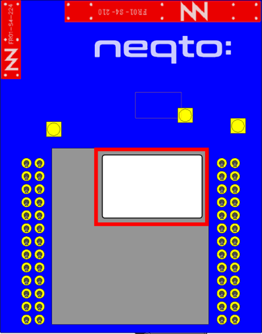
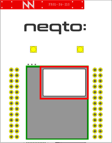
01. NEQTO Bridge Module
Overview
The NEQTO Engine installed on the NEQTO Bridge Module makes it easy to connect to NEQTO Console and the customer's cloud environment. It also allows customers to easily control sensors and devices via physical interfaces.
It has the following features:
- Wi-Fi, LTE Cat.1, LTE Cat.M1, LTE Cat.NB1(*1), LAN(*2) communications are supported.
*1: Please contact us if you would like Cat.NB1.
*2: Please refer to LAN Module Installation. - Because each module is designed under a common interface, it is easy to replace modules.
- Built-in Antenna (If you would like an external antenna, please contact us.)
- 3.0 V - 5.25 V operating voltage range.
- Low-power functionality
- Photocouplers and MOS relays can transmit signals while electrically isolated from the customer's circuit, and can drive a 12 V interface. (24V interface is available for MOS relay)
Main Specifications (NEQTO Bridge Module Common Specs)
| Item | Specs | Notes |
|---|---|---|
| CPU | STM32L4R5 (Cortex®-M4 / ROM 2MB / RAM 640KB) | |
| Flash ROM (External) | 16 MB | |
| Digital I/O | UART x 2 ch SPI x 2 ch I2C x 2 ch GPIO x 13 ch NRST USER_SW SYSTEM_LED_BLUE SYSTEM_LED_RED | |
| Photo coupler input | 1 ch NODE1_PhotoMOS_IN | 12 VDC, 4 mA |
| MOS Relay Output | 1 ch NODE1_RELAY_OUT | - Relay contact: 1a - Control capacity 24 VDC, 0.5 A |
| Analog Input | 2 ch ANALOG1, ANALOG2 | Conversion voltage range: 0 - VREF+ = 3.3V (Note 1) |
| Connector | 2.00 mm Pitch pin header 26 pin x 2 | PSS-220153-13 (Hirosugi Keiki Co.,Ltd.) |
| Main Power Supply (VDD_BATT) | 3.0 V - 5.25 V | 2 A@5 V recommended |
| RTC Power Supply (VDD_RTC) | 1.55 V - 3.6 V | Open when not in use. |
| Operating Temperature Conditions | -10 ℃ - 50 ℃ | |
| Storage Temperature Conditions | -10 ℃ - 50 ℃ |
- Note 1) VREF+ is the input reference voltage of the ADC, supplied by the regulator (XC6215B332GR-G) on the NEQTO Bridge Module. The output deviation of the XC6215B332GR-G is 3.3 V ± 2 %.
Pinout (NEQTO Bridge Module Common Specs)
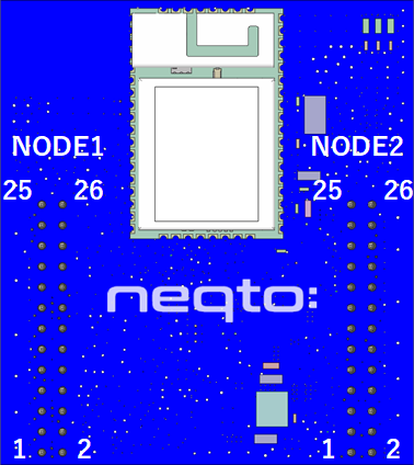
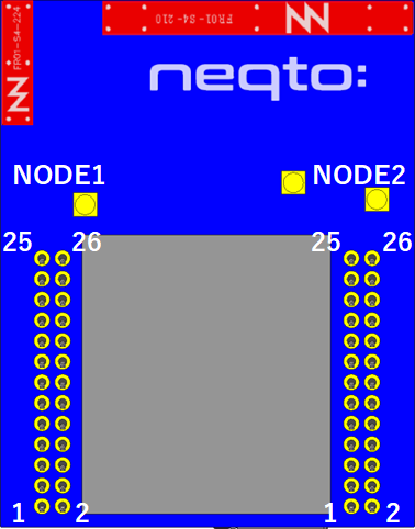
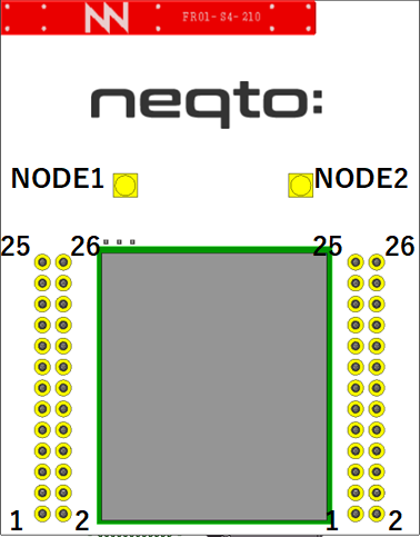
| NODE1 | |||||||
|---|---|---|---|---|---|---|---|
| neqto.js Interface | Notes | Pin Name | Pin No. | Pin Name | Notes | neqto.js Interface | |
| - | Ground | GND | 25 | 26 | GND | Ground | - |
| - | RTC Power Supply Input | VDD_RTC | 23 | 24 | GND | Ground | - |
| - | Reset Input | NRST | 21 | 22 | VDD_BATT | Power Supply Input | - |
| ADC(2) | ADC Input 2 | ANALOG2 | 19 | 20 | VDD_BATT | Power Supply Input | - |
| ADC(1) | ADC Input 1 | ANALOG1 | 17 | 18 | NODE1 IO6 | GPIO PWM (Note 2) | GPIO(16) |
| GPIO(10) | GPIO INT | NODE1 IO0 | 15 | 16 | NODE1 IO5 | GPIO PWM (Note 2) | GPIO(15) |
| UART(1) | UART CTS Input | NODE1 UART_CTS | 13 | 14 | NODE1 PhotoMOS_IN2 | Photo Coupler Input (Note 4) INT WAKEUP (Note 5) | GPIO(13) |
| UART RTS Output | NODE1 UART_RTS | 11 | 12 | NODE1 PhotoMOS_IN1 | |||
| UART Reception Data Input | NODE1 UART_RX | 9 | 10 | NODE1 RELAY_OUT2 | Relay Output (Note 3) PWM (Note 1) | GPIO(11) | |
| UART Transmission Data Output | NODE1 UART_TX | 7 | 8 | NODE1 RELAY_OUT1 | |||
| I2C(1) | I2C Serial Clock Output | NODE1 I2C_SCL | 5 | 6 | NODE1 I2C_SDA | I2C Serial Data I/O | I2C(1) |
| SPI(1) | SPI Data Input | NODE1 SPI_MISO | 3 | 4 | NODE1 SPI_SCK | SPI Serial Clock Output | SPI(1) |
| SPI Data Ouput | NODE1 SPI_MOSI | 1 | 2 | NODE1 SPI_NCS | SPI Chip Select Output | ||
| NODE2 | |||||||
|---|---|---|---|---|---|---|---|
| neqto.js Interface | Notes | Pin Name | Pin No. | Pin Name | Notes | neqto.js Interface | |
| - | Ground | GND | 25 | 26 | GND | Ground | - |
| - | Power Supply Input | VDD_BATT | 23 | 24 | NODE2 IO9 | GPIO INT | GPIO(29) |
| UserSW | User Switch Input WAKEUP | USER_SW | 21 | 22 | NODE2 IO8 | GPIO | GPIO(28) |
| - | System LED (Red) Output | SYSTEM_LED RED | 19 | 20 | NODE2 IO7 | GPIO | GPIO(27) |
| - | System LED (Blue) Output | SYSTEM_LED BLUE | 17 | 18 | NODE2 IO6 | GPIO INT | GPIO(26) |
| GPIO(20) | GPIO INT WAKEUP | NODE2 IO0 | 15 | 16 | NODE2 IO5 | GPIO INT | GPIO(25) |
| UART(2) | UART CTS Input | NODE2 UART_CTS | 13 | 14 | NODE2 IO4 | GPIO INT | GPIO(24) |
| UART RTS Output | NODE2 UART_RTS | 11 | 12 | NODE2 IO3 | GPIO INT | GPIO(23) | |
| UART Reception Data Input | NODE2 UART_RX | 9 | 10 | NODE2 IO2 | GPIO INT | GPIO(22) | |
| UART Transmission Data Output | NODE2 UART_TX | 7 | 8 | NODE2 IO1 | GPIO INT | GPIO(21) | |
| I2C(2) | I2C Serial Clock Output | NODE2 I2C_SCL | 5 | 6 | NODE2 I2C_SDA | I2C Serial Data I/O | I2C(2) |
| SPI(2) | SPI Data Input | NODE2 SPI_MISO | 3 | 4 | NODE2 SPI_SCK | SPI Serial Clock Output | SPI(2) |
| SPI Data Ouput | NODE2 SPI_MOSI | 1 | 2 | NODE2 SPI_NCS | SPI Chip Select Output | ||
- All unused pins except NRST and USER_SW can be left open (not connected).
- VDD_RTC(1.55 V to 3.6 V) can be left open when RTC power is not supplied from a battery independent of the system power supply (VDD_BATT).
- Input terminals other than NRST (reset input), ANALOG1 (ADC input 1), ANALOG2 (ADC input 2) and NODE1_PhotoMOS_IN (photocoupler input) have a 5 V tolerant function. However, note that the digital output of the NEQTO Bridge Module is a 3.3 V output. (Excluding NODE1_RELAY_OUT (relay output))
- For digital output voltage, refer to Interface Specifications.
- Note 1) When using PWM output with GPIO11, the pulse cycle that can be specified is up to 100 ms.
- Note 2) Since the PWM function of GPIO15 and GPIO16 uses the same signal generation source, two ports can generate phase-synchronized pulses. You can specify the pulse period and pulse width for each of the GPIO15 and GPIO16 ports by the neqto.js GPIO object, but the pulse period that is last set out of these two port settings will be applied. Although different pulse periods are not possible, the pulse width can be set for each port.
- Note 3) GPIO11 can be set only GPIO operation mode
5(OUT/PUSH-PULL)or9(OUT/PWM). The contact configuration is "1a (SPDT-NO)". For the connection of the relay, refer to the block diagram of each module. - Note 4) GPIO13 can be set only GPIO operation mode
2(IN). In addition, the signal polarity obtained from GPIO is opposite to that of the photo coupler input. For the connection of the photo coupler, refer to the block diagram of each module. - Note 5) Some NEQTO Bridge Module have restrictions on the wakeup function of GPIO13.
Please check the NEQTO Bridge Module you are using.NEQTO Bridge Module Restrictions - LTE-1 There are no restrictions. - Wi-Fi
- LTE-M/NBIf the last 8 digits of the serial ID is 00000001 to 00001000 :
GPIO13 wakeup function is not supported.
Instead, GPIO10 supports wakeup function.
If the last 8 digits of the serial ID is 00001001 or later :
There are no restrictions.
Interface Specifications (NEQTO Bridge Module Common Specs)
Electrical Characteristics
| Item | Specs | Notes |
|---|---|---|
| Low Level Input Voltage | Max 0.99 V@VDDIOx = 3.3 V (Note 1) | UART / SPI / I2C / GPIO / NRST / USER_SW |
| High Level Input Voltage | Min 2.31 V@VDDIOx = 3.3 V (Note 1) | UART / SPI / I2C / GPIO / NRST / USER_SW |
| Low Level Output Voltage 1 | Max 0.45 V@IOL = 4 mA, VDDIOx = 3.3 V (Note 1) | UART / SPI / GPIO |
| Low Level Output Voltage 2 | Max 0.4 V@IOL = 3 mA, VDDIOx = 3.3 V (Note 1) | I2C |
| High Level Output 1 | Min 2.85 V@IOH = 4 mA, VDDIOx = 3.3 V (Note 1) | UART / SPI / GPIO |
| High Level Output 2 | SDA, SCL Line is VDDIOx = 3.3 V (Note 1) 4.7 kΩ pull-up | I2C |
| LED drive signal SYSTEM_LED_BLUE SYSTEM_LED_RED | High Leve Output 2.9 V@8 mA, VDDIOx = 3.3 V (Note 1) 2.0 V@20 mA, VDDIOx = 3.3 V (Note 1) | SYSTEM_LED_BLUE and SYSTEM_LED_RED signal are source driven. |
- Note 1) VDDIOx is supplied by the regulator (XC6215B332GR-G) on the NEQTO Bridge Module. The output deviation of the XC6215B332GR-G is 3.3 V ± 2 %.
Supported Baudrates
| Item | Specs | Notes |
|---|---|---|
| NODE1 UART Baudrate | 2,400 bits/s - 921,600 bits/s | |
| NODE2 UART Baudrate | 2,400 bits/s - 921,600 bits/s In case of User Console Mode, Baud rate is fixed 921,600 bits/s and uses NODE2 UART. | |
| NODE1 SPI Baudrate | 0.15625M bits/s - 20M bits/s | |
| NODE2 SPI Baudrate | 0.15625M bits/s - 20M bits/s | |
| NODE1 I2C Baudrate | 100k bits/s, 400k bits/s | |
| NODE2 I2C Baudrate | 100k bits/s, 400k bits/s |
Pin Initial Values
| Function | Pin Name | Initial value | Notes |
|---|---|---|---|
| UART | NODE1_UART_TX | Default High | |
| NODE1_UART_RX | Internal PULL-UP | ||
| NODE1_UART_RTS | Default High | ||
| NODE1_UART_CTS | Internal PULL-UP | ||
| UART | NODE2_UART_TX | Default High | |
| NODE2_UART_RX | Internal PULL-UP | ||
| NODE2_UART_RTS | Default High | ||
| NODE2_UART_CTS | Internal PULL-UP | ||
| SPI | NODE1_SPI_MOSI | Internal PULL-UP | |
| NODE1_SPI_NCS | Internal PULL-UP | ||
| NODE1_SPI_MISO | Internal PULL-UP | ||
| NODE1_SPI_SCK | Internal PULL-UP | ||
| SPI | NODE2_SPI_MOSI | Internal PULL-UP | |
| NODE2_SPI_NCS | Internal PULL-UP | ||
| NODE2_SPI_MISO | Internal PULL-UP | ||
| NODE2_SPI_SCK | Internal PULL-UP | ||
| I2C | NODE1_I2C_SCL | External PULL-UP 4.7 kΩ | |
| NODE1_I2C_SDA | External PULL-UP 4.7 kΩ | ||
| I2C | NODE2_I2C_SCL | External PULL-UP 4.7 kΩ | |
| NODE2_I2C_SDA | External PULL-UP 4.7 kΩ | ||
| GPIO | NODE1_IO0 | GPIO operation mode: 0 (IN/PULL-UP) | |
| NODE1_IO5 | GPIO operation mode: 0 (IN/PULL-UP) | ||
| NODE1_IO6 | GPIO operation mode: 0 (IN/PULL-UP) | ||
| NODE2_IO1 | GPIO operation mode: 0 (IN/PULL-UP) | ||
| NODE2_IO2 | GPIO operation mode: 0 (IN/PULL-UP) | ||
| NODE2_IO3 | GPIO operation mode: 0 (IN/PULL-UP) | ||
| NODE2_IO4 | GPIO operation mode: 0 (IN/PULL-UP) | ||
| NODE2_IO0 | GPIO operation mode: 0 (IN/PULL-UP) | ||
| NODE2_IO5 | GPIO operation mode: 0 (IN/PULL-UP) | ||
| NODE2_IO6 | GPIO operation mode: 0 (IN/PULL-UP) | ||
| NODE2_IO7 | GPIO operation mode: 0 (IN/PULL-UP) | ||
| NODE2_IO8 | GPIO operation mode: 0 (IN/PULL-UP) | ||
| NODE2_IO9 | GPIO operation mode: 0 (IN/PULL-UP) | ||
| Relay Output | NODE1_RELAY_OUT1 | GPIO operation mode: 5 (OUT) | Low: RELAY OFF (Default) High: RELAY ON |
| NODE1_RELAY_OUT2 | |||
| Photo Coupler Input | NODE1_PhotoMOS_IN1 | GPIO operation mode: 2 (IN) | Low: Voltage between IN1-IN2 pins is applied High: Voltage between IN1-IN2 pins is not applied (Default) |
| NODE1_PhotoMOS_IN2 | |||
| Reset Input | NRST | Internal PULL-UP | Low: Reset High: Normal (Default) * To reset, hold Low for 1 ms or more. |
| User Switch Input | USER_SW | Internal PULL-DOWN | Low: OFF (Default) High: ON |
| System LED Output | SYSTEM_LED_BLUE | - | Low: OFF High: ON |
| SYSTEM_LED_RED | - | Low: OFF High: ON |
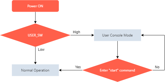
About User Console Mode
The User Console Mode provides a command console interface using the UART interface.
It is available for inputting various settings commands and displaying real-time logs.
When the power is turned on while the USER_SW signal is High, the User Console mode is activated.
Note that it is required to configure the NEQTO Bridge Module communication settings from the User Console mode. Therefore, it will be necessary to prepare a method to control the logic of USER_SW.
About Serial ID
The NEQTO Bridge Module is assigned a 16-digit serial ID.
This serial ID is a unique number for each NEQTO Bridge Module.
The upper 8 digits of the serial ID indicates the type of the NEQTO Bridge Module and is a unique number for each type.
The last 8 digits are the serial number assigned at the time of manufacture.
| NEQTO Bridge Module Type | Upper 8 digits of Serial ID | Last 8 digits of Serial ID |
|---|---|---|
| NEQTO Bridge LTE-M/NB | 00910000 | 00000000 - 99999999 |
| NEQTO Bridge Wi-Fi | 01010000 | 00000000 - 99999999 |
| NEQTO Bridge LTE-1 | 01610000 | 00000000 - 99999999 |
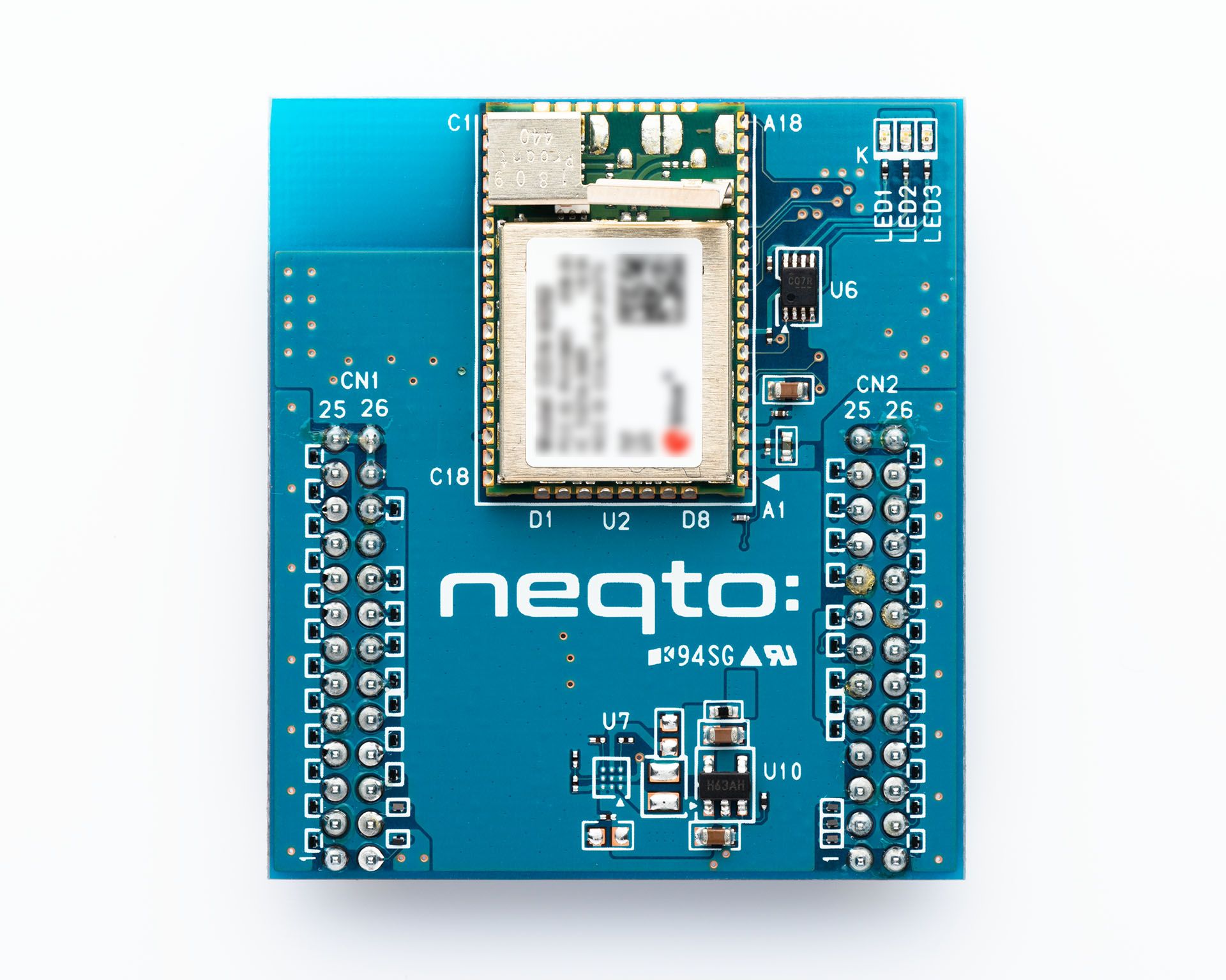
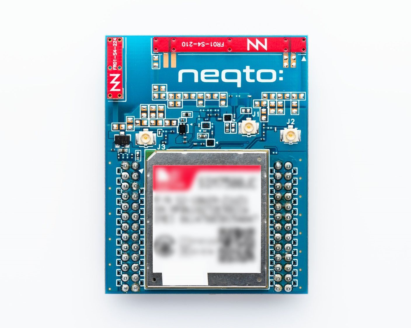
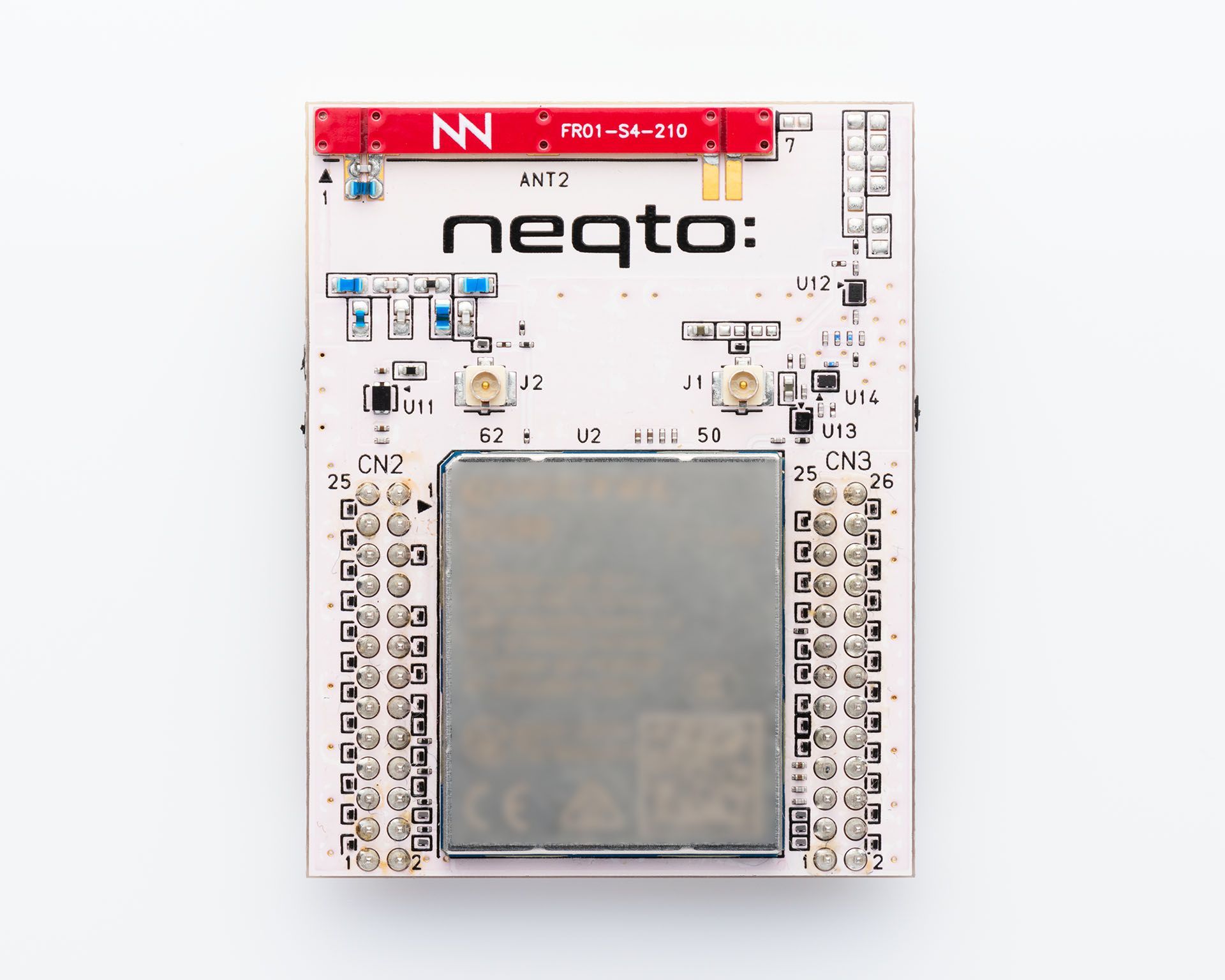
About QR Code
A QR code label is attached to the NEQTO Bridge Module.
The location of the QR code label varies depending on the NEQTO Bridge Module type.
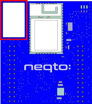
Shown on the QR code label are the QR code and the serial ID (16 digits).
The QR code contains the ',' separated serial ID (16 digits) and the product key (16 alphanumeric characters).
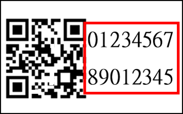 |
QR code data (serial ID,product key) 0123456789012345,ABCDEFGHJK123456 |
The serial ID and product key are required to register the device on the NEQTO Console.